STAR TRAC FITNESS TM E Series Treadmill Install Guide
ASSEMBLY AND SETUP UNPACKING Remove all parts from the shipping crate and verify that the following parts were included in your shipment: Description Qty. Installation Instructions E-TR & E-TRx . . . . . . . . . . . . . . . . . . . . . . . . . . . . . . . . . . . . . . . . . . . . . . 1 Tie Strap, 14* . . . . . . . . . . . . . . . . . . . . . . . . . . . . . . . . . . . . . . . . . . . . . . . . . . . . . . . . . . . . . . . . . . 1 Screw, Truss Head, #10-24 x 3/4* . . . . . . . . . . . . . . . . . . . .
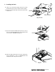
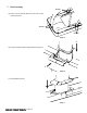
2. Installing the Neck 2a) Pop out the Front Motor Shroud Cap from the Motor Shroud and remove the Neck Grommet and set it aside. 2b) Remove the Motor Shroud by removing the (2) #10 Truss head screws. Screws Motor Shroud Motor Shroud Cap Step 2a & 2b 2c) Insert neck as shown and fasten with (2) 5/16-18 x 3.0”, (2) 5/16-18 x 1.0” socket head screws, (4) 5/16 washers and (4) lock washers. DO NOT fully tighten yet.
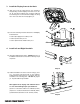
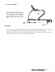
3. Install the Display frame to the Neck 3a) Take care to route the cables from the neck carefully to aviod pinching, mount the display unit onto the neck. Use the 1/4” Hex Allen to install the four (4) Socket Head Cap Screws through the neck mount into the display unit, using the 4 inner holes. Note: Do not fully tighten yet.
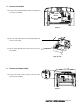
. Connect the Cables 5a) Locate the DC Powerboard and the Motor Control board in the front of the treadmill. DC Power Board Motor Control Board Step 5a 5b) Take the cable labeled Motor Control Board (MCB) and connect it to the MCB. 5c) Take the cable labled DC Power and connect it to the DC Power Board. Step 5b & 5c 6. Connect the Power Cable 6a) Connect the female end of the power cord to the under side front of the treadmill.
7. Final Assembly Screws 7a) Fasten motor shroud and Side Bed Covers with (6) #10 Truss Head screws. Screws Screws Step 7a 2 7b) Pop in Front Motor Shroud Cap and install Neck Grommet. 1 Step 7b 7c) Install Handrail Grommet.
. Level the Tread Mill Before you plug in the treadmill, make sure it is where you plan to use it and it is level to the ground. If necessary, level your treadmill using the two adjustable feet under the tailroller. Loosen the lock nuts, rotate the feet until the treadmill is stabilized, and retighten the lock nuts. Leveling Feet ATTENTION Star Trac recommends that treadmills be spaced a minimum of 20.0 inches (0.5 m) apart to allow safe and easy ingress and egress.