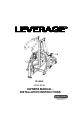
IP-L3005 HIGH ROW OWNERS MANUAL INSTALLATION INSTRUCTIONS
Copyright 2011. Star Trac by CORE INDUSTRIES. All rights reserved, including those to reproduce this book or parts thereof in any form without first obtaining written permission from Star Trac. Every effort has been made to keep this information current; however, periodically, changes are made to the information herein, and these changes will be incorporated into new editions of this publication. All product names and logos are trademarks of their respective owners. Printed in the USA.
TABLE OF CONTENTS • SAFETY INSTRUCTIONS / WARNINGS 4 • WARNING LABLES WITH PART NUMBERS 6 • EXERCISE GUIDELINES 7 • MAINTENANCE AND SERVICE 8 • WARRANTY COVERAGE 9 • INSTALLATION INSTRUCTIONS 11 • HARDWARE 18 Page 3
Safety Instructions LEVERAGE Safety Information and General Exercise Guidelines Safety Information Read the LEVERAGE Owner's Manual carefully before assembling, servicing or using the LEVERAGE. ! WARNING: Serious injury or death could occur if these safety precautions are not observed: 1. Do not use the LEVERAGE in any way other than designed or intended by the manufacturer. It is imperative that the LEVERAGE as well as any other STAR TRAC STRENGTH equipment is used properly to avoid injury. 2.
13. SECURING EQUIPMENT: All STAR TRAC equipment MUST be secured to the floor to stabilize and eliminate rocking or tipping over. This must be performed by a licensed contractor. DO NOT use the Weight equipment if it is not set up and located on a solid level surface. 14. Make sure that each machine is set up and operated on a solid level surface. DO NOT install equipment on an uneven surface.
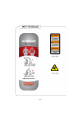
731-3081 Page 6
Exercise Guidelines • Like most exercise, strength training involves an element of risk. Utilize this information to assist you and/or your members in making the experience on STAR TRAC equipment both productive and safe. • Prior to engaging in any strength-training program, individuals with known health conditions and/or individuals whom are unfamiliar with the risk (s) involved with weight training, should first consult with a physician.
MAINTENANCE AND SERVICE LEVERAGE requires very little upkeep to keep your equipment performing at its best, the following guidelines are suggested. GENERAL CLEANING Wipe LEVERAGE with a light all-purpose cleaner, such as diluted Simple Green at a 30:1 solution. Dry LEVERAGE with a soft cloth to prevent rust. BEARING GREASE PACKING Before bearings 731-0842 and 731-2595 installed they must be fully packed with general purpose Lithium Grade 2 grease.
Warranty Coverage Star Trac commercial exercise equipment (.Product.) is warranted to be free of all defects in material and workmanship. Star Trac warrants all structural frameworks for a period of 10 years. This limited warranty on structural frame does not include coatings. The following moving parts are warranted for 5 years; rotary bearings and structural moving parts. All unlisted parts, handles and accessories are warranted for 1 year. Upholstery is warranted for 6 months.
Exclusive warranties THIS LIMITED WARRANTY IS IN LIEU OF ALL OTHER WARRANTIES OF ANY KIND EITHER EXPRESSED OR IMPLIED, INCLUDING BUT NOT LIMITED TO THE IMPLIED WARRANTIES OF MERCHANTABILITY AND FITNESS FOR A PARTICULAR PURPOSE, AND ALL OTHER OBLIGATIONS OR LIABILITIES ON OUR PART. We neither assume nor authorize any person to assure for us any other obligation or liability concerning the sale of this Product.
INSTALLATION INSTRUCTIONS REQUIRED TOOLS: • 13mm Box / Open-End Wrench ………………..... • 13mm Socket…………………………………………… • Torque Wrench………………………………………… 1 1 1 • 5mm Hex Key Socket…………………………………... • 6mm Hex Key Socket…………………………………… 1 1 GENERAL NOTES: • Unless otherwise noted Loctite 242/243 or equivalent thread locker must be used on all threaded fasteners. (Do not use thread locker when a Nyloc nut is used.) • All Star Trac Strength equipment MUST be secured to the floor using either 10mm or 3/8in.
STEP #1 - UNPACK AND ASSEMBLE MAIN FRAME: 1. Remove and unwrap all product from shipping boxes. Lay all parts out in a clean open area to prepare for assembly. 2. Locate the FRONT FRAME, MAIN FRAME, and REAR FRAME as shown below. 3. Slide FRONT FRAME into MAIN FRAME. Loosely Install three (M8 X 25MM, BUTTON HEAD BOLTS), and three (M8, FLAT WASHERS) do not tighten at this time. 4. Slide REAR FRAME into MAIN FRAME.
STEP #2 - ASSEMBLE SIDE FRAMES: 1. Locate the SIDE FRAME LEFT, AND SIDE FRAME RIGHT as shown below. 2. As shown slide SIDE FRAME LEFT into STEP #1 ASSEMBLY. At each tube joint loosely Install three (M8 X 25MM, BUTTON HEAD BOLTS), and three (M8, FLAT WASHERS) do not tighten at this time. 3. As shown slide SIDE FRAME RIGHT into STEP #1 ASSEMBLY. At each tube joint loosely Install three (M8 X 25MM, BUTTON HEAD BOLTS), and three (M8, FLAT WASHERS) do not tighten at this time. 4.
STEP #3 – ASSEMBLE UPPER ARM ASSY AND LOWER LEVERAGE ARMS : 1. Locate one of the Upper Arm Assembly ,one of the Lower Leverage Arm and slide them onto the corresponding shaft as shown below. The side of the them that has the bearing and seal pre-installed will slide onto the corresponding shaft first. 2.After the Upper Arm Assembly and Lower Leverage Arm have been slid onto the corresponding shaft install a fully greased (20MM ID TAPERED BEARING) with the small diameter of the bearing going first.
STEP #4: INSTALL LINKAGE BARS 1. Locate one of the Linkage Bars to install. On the end with the spherical rod, insert two misalignment bushings and two O-rings, one bushing and one O-ring on each side of the rod end as shown below. 2. Slide the assembled rod end into the stainless steel strap bracket then install one (M10 X 40MM, SHOULDER BOLT), two (M10 FLAT WASHERS), and a (M8, NYLOCK NUT). Tighten to specified torque using a 5MM hex key,13MM sockettorque wrench. 3.
STEP #5: INSTALL KNEE PAD ASSEMBLY, SUPPORT BEAMS 1. Install the SUPPORT BEAM using FOUR (M8 X 25MM, BUTTON HEAD SCREWS) four (M8,FLAT WASHERS). Tighten all the screws at this time. 2. Repeat steps 1 to install the another SUPPORT BEAM as shown below. 3. Insert the CHEST PAD into PAD FRAME make sure the holes face the handle bar, align the pop pin of handle bar and fixed the KNEE PAD as shown below.
STEP #6 – INSTALL WEIGHT STORAGE, BEARING END CAPS: 1.Install the WEIGHT HORN weldment and BACKING PLATE using two (M8 X 75MM, SOCKET HEAD BOLTS) four (M8,FLAT WASHERS) and two (M8, NYLOCK NUTS). Tighten to specified torque using a 6MM hex key and 13MM wrench. 2. Slide the COVER and PLASTIC SLEEVE onto WEIGHT HORN weldment. Install the rubber END CAP using one ( M8x25MM, SOCKET HEAD BOLT), one (M8, FLAT WASHER) as shown. 3.Repeat steps 1 and 2 to install all four weight storage horns. 4.
HARDWARE 731-0390 - M8*25mm Page 18
FINAL ASSEMBLE CHECK SHEET 1. Make sure ALL fasteners are tightened to specifications is this manual. 2. See Maintenance and Service page. 1. Perform all steps MACHINE CLEARANCE AND SPACING For the safe operation of Leverage Strength™ Star Trac recommends that a clearance of 24 inches (60.96cm) be maintained between and behind machines including moving arms and levers. To insure safe entry and exit to each unit a walkway of at least 36 inches (91.
STAR TRAC 14410 Myford Road Irvine, California 92606 Telephone: (800) 228-6635, (714) 669-1660 Fax: (714) 508-3303 www.startrac.com Part No. 620-8083, Rev A.