SERVICE HANDBOOK SandBlaster ® Self Cleaning Commercial Gas Water Heaters with Flue Damper and Electronic Ignition M O D E L S C O V E R E D SBD71 120 Through SBD85 500 Also includes Parts List Prepared by the State Water Heaters Training Department. For additional technical information call 800-365-0577. State Water Heaters COMMERCIAL The Expert’s Choice® ©Copyright 2006 State Industries, Inc. 500 Tennessee Waltz Parkway Ashland City, TN 37015 800-365-8170 www.statewaterheaters.
SBD TANK TYPE HEATERS SERVICE HANDBOOK SBD HANDBOOK TABLE OF CONTENTS PAGE Introduction 1-2 Installation Clearances Air Requirements Contaminated Air Flammable Gas Pressure Gas Valve Venting 3 4 5-8 9 9 10 11 12-15 Sequence of Operation Mechanical Electrical 16 17-18 Troubleshooting Transformer High Limit Damper (on Standby) PC Board Thermostat Effikal Damper Effikal Harness Test Normal Operation 19 20-21 22 22-23 24 25 26 26-27 PAGE Troubleshooting (continued) Troubleshooting the Efflkal Wire Harne
SBD TANK TYPE HEATERS SERVICE HANDBOOK Qualifications: Installation or service of this water heater requires ability equivalent to that of a licensed tradesman in the field involved. Plumbing, air supply, venting, gas supply and electrical testing skills are required.
SBD TANK TYPE HEATERS SERVICE HANDBOOK INSTALLATION This portion of the handbook will review some often overlooked installation considerations, taking note of necessary installation requirements for the SBD 71120 through SBD 85500 model heaters. The installation manual covers most of these items in detail. CLEARANCES FROM COMBUSTIBLES Clearance to Combustibles Table MODEL 120 - 200 250 - 305 365 - 400 500 A 1” (2.54CM) 2” (5.08CM) 3” (7.75CM) 5” (12.7CM) B 1” (2.54CM) 2” (5.08CM) 3” (7.75CM) 5” (12.
SBD TANK TYPE HEATERS SERVICE HANDBOOK EXTERIOR CLEARANCE "Copyright by the American Gas Association. Used by permission of the copyright holder". This illustrates the exterior roof clearances for SBD units with natural draft venting. The vent shall extend at least 3 feet above the highest point where it passes through a roof of a building, and at least 2 feet higher than any portion of a building within a horizontal distance of 10 feet (for vents of 12" in diameter or less). (NFPA 54 ANSI Z 223.1 SEC 7.
SBD TANK TYPE HEATERS SERVICE HANDBOOK AIR FOR COMBUSTION 10 CUBIC FEET OF AIR PER 1,000 BTU 1 ,0 0 0 BTU + 10 CU. FT. COMB. AIR (Minimum) 2.5 CU. FT. EXCESS AIR Stoichiometric or theoretical complete combustion requires 10 cubic feet of air per 1000 BTUH input of the gas input. The National Fuel Gas Code also recommends an additional 2.5 cu.ft. of "excess" air. This 12.5 cu.ft minimum supply air per 1000 BTUH input applies to natural and propane gas models.
SBD TANK TYPE HEATERS SERVICE HANDBOOK MAKE-UP AIR DIRECT COMMUNICATION 1 Square Inch Per 4,000 BTUH A fresh supply of make-up air for combustion can be supplied to the heater through makeup air ducts which directly communicate with the out of doors. Two openings are required - one within 12 inches of the top of the enclosure and one within twelve inches of the bottom of the enclosure.
SBD TANK TYPE HEATERS SERVICE HANDBOOK MAKE-UP AIR VERTICAL DUCTS 1 Square Inch Per 4,000 BTUH Often it is more practical to install vertical make-up air ducts to the out doors. Again, two openings are required - one within 12 inches of the top of the enclosure and one within twelve inches of the bottom of the enclosure. Each opening shall have a free area of not less than 1 square inch per 4000 BTUH of the total input of all appliances within the enclosure.
SBD TANK TYPE HEATERS SERVICE HANDBOOK INSUFFICIENT MAKE-UP AIR BACKDRAFT Insufficient make-up air is a major cause of combustion problems. One common example is in a restaurant installation where exhaust vent equipment was not considered in sizing make-up air requirements. This may result in air being backdrafted by the restaurant exhaust equipment through the heater causing flue gas spillage, flame roll out, improper combustion, inconsistent pilot operation, and/or erratic heater shut down.
SBD TANK TYPE HEATERS SERVICE HANDBOOK CONTAMINATED AIR Along with adequate make-up air, the quality of the air is important. Contaminants in combustion air can lead to premature heater failure. Vapors from bleaches, soaps, waxes, salts, etc. are drawn into the combustion chamber with the make-up air and, once fired, mix with water vapor in the gases to form extremely corrosive hydrochloric or hydrofluoric acid and other corrosive byproducts.
SBD TANK TYPE HEATERS SERVICE HANDBOOK GAS PRESSURE REQUIREMENTS Supply Gas Manifold Pressure Tap Dirt Leg Manifold Gas Port Maximum Supply Pressure Natural Gas 10.5" W.C. Propane Gas 13.8" W.C. Minimum Supply Pressure 5.0" W.C. 11" W.C. Manifold Pressure 4.0 " W.C. 10" W.C. The supply gas pressure is normally measured at the dirt leg or at the gas pressure tapping on the gas supply shutoff valve. This reading must be measured with 'flowing' gas.
SBD TANK TYPE HEATERS SERVICE HANDBOOK SBD GAS VALVE The gas valves used on all SBD water heaters are 24 volt AC combination step opening gas valves. They incorporate the pilot valve, main valve, and gas pressure regulators into one body. The inlet view of the valve features a filter screen and the top knob. The top knob is a manual on/off gas control for both the pilot and main gas valves. When the top knob is placed on the black mark, gas is supplied only to the pilot valve.
SBD TANK TYPE HEATERS SERVICE HANDBOOK VENTING Atmospheric, Single, and Multiple Heaters All SBD water heaters are classified by ANSI as category I (non-condensing, negative pressure venting) appliances. They are approved for type B vent. For larger applications, SBD water heaters can be common vented together either in a tapered manifold or constant size manifold. (Follow National Fuel Gas Code requirements for sizing and installation.
SBD TANK TYPE HEATERS SERVICE HANDBOOK Nine Rules for Good Vents (continued) 2. The diameter of a vent pipe should NEVER be reduced, no matter what the circumstances. 3. In some cases it may be necessary to run a vent larger than the draft diverter outlet. 4. Take the maximum vertical rise possible immediately above the draft diverter. 5.
SBD TANK TYPE HEATERS SERVICE HANDBOOK Nine Rules for Good Vents (continued) 6. Horizontal pipe should be sloped upward at a minimum of ¼” per foot. 7. Horizontal elements should be limited to 75% of the vertical rise of the vent above the connection. 8. Flue gases must be kept hot for proper venting. The vent pipe should be extended to meet local codes 9. Obstructions can cause down drafts.
SBD TANK TYPE HEATERS SERVICE HANDBOOK POWER VENT KITS FOR SIDEWALL VENTING Female plug to Damper 40’, Power Venter cable with “Y” connect Male plug to Cable Water Heater Models SBD-120-200 Part Number 193933-0 SBD-250-500 193933-1 SBD water heaters can be used with power vent kits for sidewall venting. State offers power vent kits for use on installations with a maximum of 100 equivalent feet of vent piping. The power vent kits also use type B vent materials.
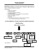
SBD TANK TYPE HEATERS SERVICE HANDBOOK SBD SEQUENCE OF OPERATION 9. Flue damper closes 2. Flue damper opens 1. Thermostat calls for heat 7. Thermostat satisfies 4. Pilot gas opens, Pilot sparks and flame proves 3. Intermittent Ignition Control 6. Main burner ignites 5. Main gas valve opens 8. Main and pilot burners "OFF" SEQUENCE OF OPERATION To understand SBD tank type water heaters, an examination of their sequence of operation is necessary.
SBD TANK TYPE HEATERS SERVICE HANDBOOK SBD ELECTRICAL SEQUENCE 100 – 109 Series Technical Training Department Ashland City, TN ©2003 17
SBD TANK TYPE HEATERS SERVICE HANDBOOK SBD ELECTRICAL SEQUENCE OF OPERATION 115/60/12A 120 VAC to Junction Box On / OFF Switch "ON" 24V Transformer Tank Temperature Calling for Heat Tank Temperature Satisfied High Limit Closed High Limit (ECO) Closed Thermostat Closed Motor Closes Damper Motor Opens Damper Cam On Damper Blade Closes Proving End Switch IID Module (24V) Receives Voltage Module (PV) Terminal Sends 24V to Pilot Coil Module (Spark) Sends 10,000V Spark to Pilot Pilot Ignites and Proves F
SBD TANK TYPE HEATERS SERVICE HANDBOOK TROUBLESHOOTING SBD WATER HEATERS To troubleshoot a SBD water heater check that: • • • 120 VAC is supplied to the heater the tank is full of water gas is supplied to the unit STEP 1 TEST THE TRANSFORMER STEP 1 - TO TEST THE TRANSFORMER - Using a multimeter, test for 24 VAC between the secondary transformer terminals. IF The meter does not read 24 VAC: THEN • Check that the 120 VAC is supplied from the On/Off Switch – if not, replace switch.
SBD TANK TYPE HEATERS SERVICE HANDBOOK STEP 2 HIGH LIMIT, LEFT TERMINAL TEST Ground 24 VAC FM Transformer STEP 2. HIGH LIMIT, LEFT TERMINAL TEST. Test for 24 VAC between the left high limit terminal and ground. IF The meter does not read 24 VAC: THEN • Check wiring between transformer and high limit. • Go to Step 3. The meter reads 24 VAC: Note: The high limit (Energy Cut Off) opens if the tank water temperature exceeds 205 degrees.
SBD TANK TYPE HEATERS SERVICE HANDBOOK TEST HIGH LIMIT RIGHT TERMINAL STEP 3 Temperature Adj. Dial High Limit (ECO) Reset Button High Limit/Thermostat Jumper Wire Black-To Damper Motor STEP 3. TO TEST HIGH LIMIT RIGHT TERMINAL. Ensure that the jumper wire between the high limit and thermostat is connected, and the damper motor power line is connected. Test for 24 VAC between the high limit right terminal and ground.
SBD TANK TYPE HEATERS SERVICE HANDBOOK STEP 4 INSPECT THE DAMPER Damper Closed Damper Open STEP 4. INSPECT THE DAMPER. Lower the thermostat setting so the unit will not be calling for heat, then inspect the damper. IF If the damper is open: If the damper is closed: THEN • Go to step 5. • Go to step 7. Note: If the water temperature in the tank is below 120 degrees F, temporarily disconnect the jumper wire between the high limit and thermostat to simulate a satisfied thermostat.
SBD TANK TYPE HEATERS SERVICE HANDBOOK STEP 6 PC BOARD MOTOR TEST Service Switch Motor Lead Motor Lead STEP 6. PC BOARD/MOTOR TEST. Check for 24 VAC between the two motor lead terminals of the PC board. Disconnect the wires for this test. IF 24 VAC is not present: THEN • Replace the Damper Drive (part # 194484) and go to step 7. The board and relay are one piece. Regardless of which part is defective, both parts should be changed.
SBD TANK TYPE HEATERS SERVICE HANDBOOK STEP 7 THERMOSTAT TEST STEP 7. THERMOSTAT TEST. Set the thermostat to call for heat. multimeter, test for 24 VAC between right terminal and ground. Using your IF THEN The meter does not read 24 VAC and the jumper wire • Replace the thermostat between the high limit and the thermostat is in place: The meter reads 24 VAC: • Go to step 8.
SBD TANK TYPE HEATERS SERVICE HANDBOOK EFFIKAL DAMPER The wiring colors from the damper PC Board are different colors than the wires on the heater wiring harness. The male/female plugs to connect the damper board to the heater harness join in only one way.
SBD TANK TYPE HEATERS SERVICE HANDBOOK HARNESS CHART Heater Harness Black Yellow Red White Function 24V Hot 24V from Thermostat 24V from damper 24V common Damper Harness 1-Brown 2-Orange 3-Yellow 4-Black NORMAL OPERATION Condition: • Heater on standby • Damper closed • High Limit closed Wires are from left to right: Black i Yellow i Brown i Orange STEP 8 TEST FOR 24VAC BETWEEN BLACK (COMMON) AND BROWN STEP 8.
SBD TANK TYPE HEATERS SERVICE HANDBOOK NORMAL OPERATION (continued) Condition: • Thermostat closed, damper in process of opening STEP 8A TEST FOR 24VAC BETWEEN BLACK AND ORANGE IF 24VAC is present 24VAC is not present THEN Continue to Step 8B. See Troubleshooting Step 9B. Condition: • Thermostat closed, damper fully open STEP 8B TEST FOR 24VAC BETWEEN BLACK AND YELLOW IF 24VAC is present 24VAC is not present Technical Training Department Ashland City, TN ©2003 THEN Continue to Step 10A.
SBD TANK TYPE HEATERS SERVICE HANDBOOK TROUBLESHOOTING THE EFFIKAL DAMPER Condition: Thermostat closed, damper closed Wires are from left to right: Black i Yellow i Brown i Orange STEP 9A TEST BETWEEN BLACK (COMMON) AND BROWN ON THE DAMPER BOARD IF 24VAC is present 24VAC is not present Technical Training Department Ashland City, TN ©2003 THEN This is correct • See Steps 1 thru 4 Check the harness plugs connecting heater and damper for looseness or damage.
SBD TANK TYPE HEATERS SERVICE HANDBOOK TROUBLESHOOTING THE EFFIKAL DAMPER (continued) Condition: Thermostat closed, damper open. Damper Open Service Switch Damper Auto STEP 9B A1 IS CORRECT, CHECK SERVICE SWITCH POSITION IF Switch is incorrect position Switch is not in correct position Technical Training Department Ashland City, TN ©2003 THEN Replace damper board/motor assembly. • Adjust switch • Cycle thermostat to verify that damper operation is correct.
SBD TANK TYPE HEATERS SERVICE HANDBOOK TROUBLESHOOTING THE EFFIKAL DAMPER (continued) Condition: Thermostat closed, damper is open fully STEP 10A TEST FOR 24VAC BETWEEN BLACK AND YELLOW IF 24VAC is present 24VAC is not present THEN This is correct – continue to Step 11 • See Step 9B. • Check the harness plug connecting. • Check that cam on shaft rotates with shaft. • Replace the damper board. • Ensure that cam is secure against end switch.
SBD TANK TYPE HEATERS SERVICE HANDBOOK STEP 11 WIRE HARNESS TEST STEP 11. WIRE HARNESS TEST. Test for 24 VAC between terminal 24V on the IID module, and 24V GND. IF 24 VAC is not present: 24 VAC is present: THEN • Check the wiring harness. • Go to step 12. Note: This test may be easier to conduct by removing the red wire from the IID terminal. Test for 24 VAC between the red wire and ground. Reconnect the red wire to the 24V terminal after the test.
SBD TANK TYPE HEATERS SERVICE HANDBOOK STEP 12 IID MODULE TEST STEP 12. IID MODULE TEST (Power to the Pilot Valve). Using a multimeter, test for 24 VAC between terminal PV and 24V (GND) on the IID during the 90 second trial for ignition. IF THEN The meter does not read 24 VAC and the • Replace the module.
SBD TANK TYPE HEATERS SERVICE HANDBOOK STEP 13 PILOT SPARK TEST STEP 13. PILOT SPARK TEST. Visually check for spark at the pilot assembly. Note: The pilot burner mounts on the left side of the main burner. IF The igniter is not sparking: THEN Check for: • A 7/64” spark gap • Spark cable continuity • Ground cable continuity • Go to step 14. Sparking is present: Power To Module May Be Interrupted To Reset . Call for heat 90 sec. 5 min.
SBD TANK TYPE HEATERS SERVICE HANDBOOK STEP 14A PILOT VALVE - OHM TEST SBD 120 – 400 GAS VALVE STEP 14A. PILOT VALVE - OHM TEST. If pilot assembly is sparking but no pilot flame is established, disconnect the pilot valve solenoid leads. Using a multimeter, (set to read ohms) test for 20* ohms resistance +/- 5 through the solenoid coil.
SBD TANK TYPE HEATERS SERVICE HANDBOOK STEP 14B PILOT VALVE TEST – SBD 500 ONLY PILOT GAS MANIFOLD PRESSURE TAP BLUE WHITE RED The MV/PV wire on the IID is connected to the white wire The MV wire on the IID is connected to the red wire. MANIFOLD GAS MANIFOLD PRESSURE TAP STEP 14B. PILOT VALVE TEST – SBD 500 ONLY. Testing the two coils of the Honeywell VR8404P 5004 gas valve used on the model SBD 500 only. Because of built in diodes, it is difficult to test for ohms resistance through these coils.
SBD TANK TYPE HEATERS SERVICE HANDBOOK STEP 15 MAIN BURNER TEST STEP 15. MAIN BURNER TEST. Visually check for main burner.
SBD TANK TYPE HEATERS SERVICE HANDBOOK STEP 16 FLAME RECTIFICATION STEP 16. FLAME RECTIFICATION Note: Flame rectification means that an alternating current (AC) signal is changed to a direct current (DC) signal. The pilot flame is the 'switch' which connects the pilot hood to the igniter and ground. If the pilot hood and igniter sensor had the same surface area, the flame 'switch' would conduct an AC signal.
SBD TANK TYPE HEATERS SERVICE HANDBOOK STEP 17 IID MODULE TEST Pilot is lit - Sparking has stopped. STEP 17. IID MODULE TEST (Power to the Main Valve). Using a multimeter, test for 24 VAC between terminal MV on the IID and 24V (GND). IF 24 VAC is not present: THEN • Replace the IID module. Conduct Step 18 before applying power to replacement module. • Go to step 18.
SBD TANK TYPE HEATERS SERVICE HANDBOOK STEP 18A MAIN GAS VALVE CHECK TH TR SBD 120 – 400 GAS VALVE STEP 18A. MAIN GAS VALVE CHECK. Disconnect wires from gas valve TH and TR terminals. Using a multimeter, test for 68 ohms plus or minus 5 between TH and TR on the main valve coil.
SBD TANK TYPE HEATERS SERVICE HANDBOOK STEP 18B MAIN GAS VALVE COIL CHECK PILOT GAS MANIFOLD PRESSURE TAP BLUE WHITE The PV wire is connected to the blue wire RED The MV/PV wire on the IID is connected to the white wire. The MV wire is disconnected from the gas valve. MANIFOLD GAS MANIFOLD PRESSURE TAP STEP 18B.
SBD TANK TYPE HEATERS SERVICE HANDBOOK GENERAL SERVICE CHART CONDITION DAMPER OPENS NO POWER TO IID MODULE PILOT LIGHTS, SPARKS CONTINUOUSLY CAUSE . DAMPER NOT FULLY OPEN SOLUTION .EFFIKAL – REPLACE DAMPER CONTROL ASSEMBLY . REPLACE DAMPER . DEFECTIVE PROTECTOR SWITCH . REPLACE PC BOARD PILOT FLAME NOT PROVING SEE FLAME RECTIFICATION - STEP 16 INTERRUPT 120 VAC POWER HEATER WILL NOT IGNITE NOT PROVING PILOT FLAME EXISTANCE . CHECK GROUND WIRE ATTACHMENT .
SBD TANK TYPE HEATERS SERVICE HANDBOOK GENERAL QUESTIONS AND ANSWERS Q. What is unique about the Canadian – SBC-CGA – models vs. U.S. SBD models? A. The Canadian models have different dimensions to meet Canadian code requirements. Q: How much electrical power is required for a SBD water heater? A: The SBD models draw approximately .7 Amps at 120VAC. Q: The units require "leg kits" to meet National Sanitation Foundation standards.
SBD TANK TYPE HEATERS SERVICE HANDBOOK SBD MODELS 120 THRU 500A PARTIAL REPLACEMENT SERIES 110-111 PARTS LIST MODELS SBD 120 THRU 500A: STANDARD AND ASME (A) SERIES 110/111 EFFIKAL DAMPER DRIVE ASSEMBLY GAS VALVES HONEYWELL VALVE SBD 500A WHITE RODGERS VALVE SBC 120 – 400A Technical Training Department Ashland City, TN ©2003 43
SBD TANK TYPE HEATERS SERVICE HANDBOOK SBD MODELS 120 THRU 500A (continued) SERIES 110-111 Technical Training Department Ashland City, TN ©2003 44
SBD TANK TYPE HEATERS SERVICE HANDBOOK SBD MODELS 120 THRU 500A (continued) SERIES 110-111 ITEM PARTS Series 110-111 SBD71120NE SBD81154NE SBD81180NE SBD100199NET SBD100199NE 1 ..........Flue Baffle ................................. 193595.............. 192199-3........... 193795-1 ......... 193696 ..............193696 3 ..........Main Burner Orifice Bracket....... 98044(3) ........... 98044(3)............ 98044(5).......... 98044(5)............98044(5) 4 ..........Main Burner .........................
SBD TANK TYPE HEATERS SERVICE HANDBOOK SBD MODELS 120 THRU 500A (continued) SERIES 110-111 ITEM ITEM PARTS SBD81190NE PARTS DESCRIPTION SBD100199NES/A SBD100250NE/A SBD65251NE/A SBD100275NE/ SBD81190NE SBD100199NES/A SBD100250NE/A SBD65251NE/A SBD100275NE/A 1 ..........Flue Baffle ................................... 193795-1....... 193889................ 193595 ................193595...........193945 3 ..........Main Burner Orifice Bracket......... 98044(5)........ 98044(5) .............
SBD TANK TYPE HEATERS SERVICE HANDBOOK SBD MODELS 120 THRU 500A (continued) SERIES 110-111 ITEM PARTS DESCRIPTION SBD65305NE/A SBD85365NE/A SBD100400NE/A SBD85500NE 1 ........... Flue Baffle........................................193595....................... 193696 ............................ 193995................ 193995 3 ........... Main Burner Orifice Bracket.............098044(7) .................. 098044(9)........................ 098044(9) ............. 098044(9) 4 ........... Main Burner ..
SBD TANK TYPE HEATERS SERVICE HANDBOOK SBD MODELS 120 THRU 500A (continued) SERIES 110-111 ITEM PARTS DESCRIPTION CGA SBD71120NE CGA SBD81154NE CGA SBD76180NE CGA SBD85199NE CGA CGA CGA CGA 1 ............. Flue Baffle......................................193595...........192199-3 ....... 193795-0 ......... 193696 3 ............. Main Burner Orifice Bracket ...........98044(3) ........98044(3) ........ 98044(5).......... 98044(5) 4 ............. Main Burner ...................................98047....
SBD TANK TYPE HEATERS SERVICE HANDBOOK SBD MODELS 120 THRU 500A (continued) SERIES 110-111 ITEM PARTS DESCRIPTION CGA SBD100199NES/A CGA CGA CGA CGA SBD100250NE/A SBD65251NE/A SBD100275NE/A SBD65305NE 1 ............ Flue Baffle.....................................193889 ............193595 ..............193595.............. 193945.........193595 3 ............ Main Burner Orifice Bracket ..........98044(5) ..........98044(5) ............98044(7) ........... 98044(5) ......98044(7) 4 ............
SBD TANK TYPE HEATERS SERVICE HANDBOOK SBD MODELS 120 THRU 500A (continued) SERIES 110-111 ITEM PARTS DESCRIPTION CGA SBD85365NE/A CGA SBD100400NE/A CGA SBD85500NE/A 1 ............ Flue Baffle................................................... 193945 ........................193995......................... 193995 3 ............ Main Burner Orifice Bracket ........................ 098044(9)....................098044(9) .................... 098044(9) 4 ............ Main Burner ..........................
SBD TANK TYPE HEATERS SERVICE HANDBOOK COMPONENT PART INFORMATION NAME DUAL CONTROLLER GAS VALVE THERMOST AT HIGH LIMIT (ECO) NATURAL GAS PROPANE GAS INTERMITENT IGNITION DEVICE CONTROL DAMPER NATURAL GAS AND PROPANE GAS COMPLETE ASSEMBLY MOTOR P.C.
SBD TANK TYPE HEATERS SERVICE HANDBOOK SBD SERVICE CHECKLIST (This service checklist may be photo copied to assist with SBD service call.) This checklist is intended to aid the Service Agent in determining that the State SBD Water Heater has been properly installed and is operating correctly. Because the circumstances of each installation may vary greatly, it is not intended to be an allinclusive list of the problems that the Service Agent may encounter.
SBD TANK TYPE HEATERS SERVICE HANDBOOK V. VI.
SBD TANK TYPE HEATERS SERVICE HANDBOOK COMMENTS Author: Terry Mulder Technical Training Department Ashland City, TN ©2003 54
SERVICE HANDBOOK SandBlaster ® Self Cleaning Commercial Gas Water Heaters with Flue Damper and Electronic Ignition M O D E L S C O V E R E D SBD71 120 Through SBD85 500 Also includes Parts List Prepared by the State Water Heaters Training Department. For additional technical information call 800-365-0577. State Water Heaters COMMERCIAL The Expert’s Choice® ©Copyright 2006 State Industries, Inc. 500 Tennessee Waltz Parkway Ashland City, TN 37015 800-365-8170 www.statewaterheaters.