Instruction Manual RESIDENTIAL GAS WATER HEATERS FOR USE ONLY IN MANUFACTURED HOMES GAMA certification applies to all residential gas water heaters with capacities of 20 to 100 gallons with input rating of 75,000 BTU/Hr. or less. C3 Technology® Gas Water Heaters meet the new ANSI Z21.10.1 standard that deals with the accidental or unintended ignition of flammable vapors, such as those emitted by gasoline. • For Your Safety • AN ODORANT IS ADDED TO THE GAS USED BY THIS WATER HEATER.
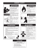
SAFE INSTALLATION, USE AND SERVICE Your safety and the safety of others is extremely important in the installation, use and servicing of this water heater. Many safety-related messages and instructions have been provided in this manual and on your own water heater to warn you and others of a potential injury hazard. Read and obey all safety messages and instructions throughout this manual.
GENERAL SAFETY
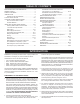
TABLE OF CONTENTS SAFE INSTALLATION, USE AND SERVICE............................2 GENERAL SAFETY..................................................................3 TABLE OF CONTENTS.............................................................4 INTRODUCTION.......................................................................4 Preparing for the New Installation......................................4 TYPICAL INSTALLATIONS................................................... 5-6 LOCATING THE NEW WATER HEATER...
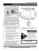
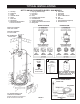
TYPICAL INSTALLATIONS GET TO KNOW YOUR WATER HEATER - GAS MODELS A Vent Pipe B Drafthood C Anode D Hot Water Outlet E Outlet F Roof Jack G Gas Supply H Manual Gas Shut-off Valve I Ground Joint Union J Drip Leg (Sediment Trap) K Inner Door L Outer door M Union N Inlet Water Shut-off Valve O Cold Water Inlet P Inlet Dip Tube/Nipple Q Temperature-Pressure Relief Valve R Rating Plate S Flue Baffle T Thermostat U Drain Valve V Pilot and Main Burner W Flue X Drain Pan Y Thermostat Shield
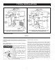
TYPICAL INSTALLATIONS INSTALLATION IN ENCLOSURE OF MANUFACTURED HOME WITH SOLID EXTERIOR DOOR INSTALLATION IN ENCLOSURE OF MANUFACTURED HOME WITH LOUVERED EXTERIOR DOOR * MIXING VALVE USAGE FIGURE 2. This appliance has been design certified as complying with American National Standard/CSA Standard for water heaters and is considered suitable for: HOTTER WATER CAN SCALD: Water heaters are intended to produce hot water.
LOCATING THE NEW WATER HEATER Facts to Consider About the Location such locations cannot be avoided, a suitable drain pan should be installed under the water heater. Drain pans are available at your local hardware store. Such a drain pan must have a minimum length and width of at least 2 inches (51 mm) greater that the water heater dimensions and must be piped to an adequate drain. The pan must not restrict combustion air flow.
Also, the water heater must be located and/or protected so it is not subject to physical damage by a moving vehicle. A gas water heater cannot operate properly without the correct amount of air for combustion. Do not install in a confined area such as a closet, unless you provide air as shown in the Typical Installations, see Figure 2 page 6. Never obstruct the flow of ventilation air. If you have any doubts or questions at all, call your gas supplier.
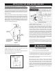
INSTALLING THE NEW WATER HEATER SECURING WATER HEATER TO FLOOR AND WALL Water Piping The water heater must be secured to the floor and to the wall of the enclosure with the three mounting brackets and screws packaged in the carton with the water heater. The two small brackets stamped #0110064 are used to attach the water heater to the floor and the one large bracket #0110063 is used to secure the top of the water heater to the wall.
The water within the water heater tank expands as it is heated and increases the pressure of the water system. If the relieving point of the water heater’s temperature-pressure relief valve is reached, the valve will relieve the excess pressure. The temperature-pressure relief valve is not intended for the constant relief of thermal expansion. This is an unacceptable condition and must be corrected.
This heater is provided with a properly certified combination temperature - pressure relief valve by the manufacturer. The valve is certified by a nationally recognized testing laboratory that maintains periodic inspection of production of listed equipment of materials as meeting the requirements for Relief Valves for Hot Water Supply Systems, ANSI Z21.22 • CSA 4.4, and the code requirements of ASME.
temperature. Such temperatures may not be high enough to properly open thermally operated vent dampers. This would cause spillage of the flue gases and may cause carbon monoxide poisoning. To fill the water heater with water: 1. Close the water heater drain valve by turning the handle to the right (clockwise). The drain valve is on the lower front of the water heater. Vent dampers must bear evidence of certification as complying with the current edition of the American National Standard ANSI Z21.
• A drip leg (sediment trap) ahead of the gas control valve to help prevent dirt and foreign materials from entering the gas control valve. • A flexible gas connector or a ground joint union between the shut off valve and control valve to permit servicing of the unit. Be sure to check all the gas piping for leaks before lighting the water heater. Use a soapy water solution, not a match or open flame. Rinse off soapy solution and wipe dry.
Connecting the gas piping to the gas control valve of the water heater can be accomplished by either of the two methods shown in Figures 9 and 10. Contaminants in the gas lines may cause improper operation of the gas control valve that may result in fire or explosion. Before attaching the gas line be sure that all gas pipe is clean on the inside. To trap any dirt or foreign material in the gas supply line, a drip leg (sometimes called a sediment trap) must be incorporated in the piping.
. Remove the Phillips-head screw holding the pilot bracket to the burner head, see Figure 16. 9. Remove flange nuts holding inner door in place with 3/8” nut driver, see Figure 13. FIGURE 16. 16. Remove the two Phillips-head screws holding the natural burner head to the burner tube assembly, see Figure 17. 17. Using 3/8” boxed-end wrench remove the natural gas burner orifice “O” from the burner tube. Install burner orifice marked “LP” and tighten securely, see Figure 17. 18.
23. Place screwdriver in slot “C”, see Figure 19. Depress and turn counterclockwise ( ) to stop. Control screw must be in “IN” position for propane (LP) gas and in “OUT” position for natural gas. STOP! Read label “For Your Safety” located on your water heater. Maximum Supply Pressure: 10.5” W.C. for Natural Gas. 13” W.C. for Propane (L.P.) Gas. Minimum Supply Pressure: 5” W.C. for Natural Gas. 11” W.C. for Propane (L.P.) Gas. ROBERTSHAW FUEL CONVERSION INSTRUCTIONS FROM PROPANE (l.p.
14. To remove the propane (LP) gas pilot assembly, remove the Phillips-head screw holding the TCO bracket to the burner tube bracket, see Figure 24. FIGURE 21. 8. Unplug wire from igniter assembly mounted on the side of the gas valve. 9. Remove flange nuts holding inner door in place with 3/8” nut driver, see Figure 22. FIGURE 24. 15. Remove the Phillips-head screw holding the pilot bracket to the burner head, see Figure 25. FIGURE 25. 16.
19. Push the propane gas pilot assembly grommet out of the inner door towards the combustion chamber. 20. To install the natural gas pilot assembly, pull the igniter wire, thermostat lead, and pilot tube through the inner door hole. Reinstall the Phillips-head screw securing the TCO bracket too the burner tube. Reinstall the Phillipshead screw securing the pilot assembly to the burner head bracket. 21. Push the grommet into the inner door hole making sure the door fits into the groove in the grommet.
WHITE-RODGERS GAS VALVE 19
ROBERTSHAW GAS VALVE 20
INSTALLATION CHECKLIST BEFORE LIGHTING THE PILOT: 1. Check the gas lines for leaks. a. Use a soapy water solution. DO NOT test for gas leaks using a match or open flame. b. Brush the soapy water solution on all gas pipes, joints and fittings. c. Check for bubbling soap. This means you have leak. Turn “OFF” gas and make the necessary repairs. 2. Is the new temperature-pressure relief valve properly installed and piped to an adequate drain? See “Temperature-Pressure Relief Valve” section. 3.
TEMPERATURE REGULATION For the RobertShaw control, turn the water temperature dial counterclockwise ( ) to decrease the temperature, or clockwise ( ) to increase the temperature. Short repeated heating cycles caused by small hot water uses can cause temperatures at the point of use to exceed the thermostat setting by up to 30°F (16.7°C). If you experience this type of use you should consider using lower temperature settings to reduce scald hazards.
FOR YOUR INFORMATION START UP CONDITIONS THERMAL EXPANSION DRAFT HOOD OPERATION Check draft hood operation by performing a worst case depressurization of the building. With all doors and windows closed, and with all air handling equipment and exhaust fans operating such as furnaces, clothes dryers, range hoods and bathroom fans, a match flame should still be drawn into the draft hood of the water heater with its burner firing.
the local water heater supplier or service agency for further information concerning an Anode Replacement Kit and this chlorination treatment. HYDROGEN GAS: Hydrogen gas can be produced in a hot water system that has not been used for a long period of time (generally two weeks or more). Hydrogen gas is extremely flammable and explosive.
PERIODIC MAINTENANCE Venting System Inspection You should check for sooting. Soot is not normal and will impair proper combustion. Soot build-up indicates a problem that requires correction before further use. Turn “OFF” gas to water heater and leave off until repairs are made, because failure to correct the cause of the sooting can result in a fire causing death, serious injury, or property damage. FIGURE 31. Burner Cleaning At least once a year a visual inspection should be made of the venting system.
Temperature-Pressure Relief Valve Operation ANODE ROD INSPECTION Each water heater contains at least one anode rod, which will slowly deplete while protecting the glass-lined tank from corrosion and prolonging the life of the water heater. Once the anode is depleted, the tank will start to corrode, eventually developing a leak. Certain water conditions will cause a reaction between this rod and the water.
1. Turn the gas control knob to the “OFF” position. 4. Screw the handle and cap assembly back into the drain valve and retighten using a wrench. DO NOT OVER TIGHTEN. 2. CLOSE the cold water inlet valve to the water heater. 5. Follow instructions in the “Filling The Water Heater” section. 3. OPEN a nearby hot water faucet and leave open to allow for draining. 6. Check for leaks. 4. Connect a hose to the drain valve and terminate to an adequate drain. 5.
LEAKAGE CHECKPOINTS Read this manual first. Then before checking the water heater make sure the gas supply has been turned “OFF”, and never turn the gas “ON” before the tank is completely full of water. A. Water at the draft hood is water vapor which has condensed out of the combustion products. This is caused by a problem in the vent. Contact the gas utility. B. *Condensation may be seen on pipes in humid weather or pipe connections may be leaking. C. *The anode rod fitting may be leaking. D.
30 & 40 GALLON REPAIR PARTS LIST Key No.
50 GALLON REPAIR PARTS LIST Key No.
TROUBLESHOOTING GUIDELINES These guidelines should be utilized by a qualified service agent. When calling for service notify the service agent that this is a “Flammable Vapor Ignition Resistant” Product. Problem WATER LEAKS Cause Solution Improperly sealed, hot or cold supply connection, relief valve, drain valve, or thermostat threads. Tighten threaded connections. Leakage from other appliances or water lines. Inspect other appliances near water heater. Condensation of flue products.