
User's Manual

100171-03 Water Meter Interface
Final Assembly Procedures 8000171-60-01
March 11, 2003 Page 3
© Copyright 2003,
StatSignal
Systems, Inc.
All Rights Reserved
* * C O N F I D E N T A L * *
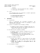
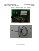
1) Drill a ½” hole in the center of lid (171401).
2) Insert the 22/3 AWG Wire Assembly (222056) through
the ½” Hole in the lid (171401) leaving 3ft of
Wire Assembly (222056) with the connector on the
inside of the Lid (171401) – see figure 2.
3) Secure Wire Assembly (222056) to the Lid (171401)
with the 1.5-5.0 mm PG7 Cord Grip (222059) -
leaving 3” of the wire (connector end) inside the
171501 Lid Assembly.
4) Coil the wire and secure with a paper tie
(999110).
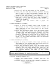
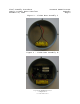
5.6 Base Assembly-I (171502)
1) Apply 1” strip of Double Stick Tape (777005) on
the bottom of the 171402 enclosure, along the
edge, with one of the screw posts at the center
(for reference).
2) Strip the protective paper from the Double Stick
Tape (777005) and press the Battery Assembly
(171500) onto the Double Stick (777005), as close
to the edge of the 171402 base enclosure as
possible, keeping the screw post as a center point
of reference and the battery leads facing the
center of the 171402 enclosure with the positive
side on the right.
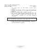
5.7 Base Assembly-II (171503)
1) Apply 1” Strip of Double Stick Tape (777005) in
the middle of the 171402 base enclosures parallel
with the Battery Assembly (171500).
2) Strip the protective paper from the Double Stick
Tape (777005) and press the 200171 Circuit Board
Assembly onto the tape making sure that the top
two corners of the 200171 Circuit Board Assembly
are pressed against the edge of the 171402
enclosure.
*** NOTE***
Before proceeding to the next step, make sure the 200171
Circuit Board Assembly is securely in place.
5.8 Final Assembly (100171-xxx)
1) Insert the O-RING Gasket (777000) into the lid
channel.
2) Connect the 3ft 22/3 AWG wire assembly (222056) to