Installation Manual B-500-MTRX-230-8x8 Binary™ HDMI Matrix Switcher with HDMI and HDBaseT Outputs
B-500-MTRX-230-8x8 Installation Manual 1. Important Safety Instructions Warning: To reduce the risk of fire or electric shock, do not expose this apparatus to rain or moisture. Do not remove cover. No user serviceable parts inside. Refer servicing to qualified service personnel. 1. Read and follow all instructions and warnings in this manual. Keep for future reference. 2. Do not use this apparatus near water. 3. Clean only with a dry cloth. 4. Do not block any ventilation openings.
B-500-MTRX-230-8x8 Installation Manual Table of Contents 1. 2. 3. 4. 5. 6. Important Safety Instructions Product Overview Package Contents Features Recommended for Installation Device Layout 6.1. Front Panel 6.2. Rear Panel 7. Installation Setup 7.1. Basic Installation Diagram 7.2. Basic Instructions 7.3. Installation Tips 7.4. Switcher Location and Placement 7.4.1. Rack Installation 7.5. HDMI Input Connections 7.6. Output Connections 7.6.1. Choosing the Correct Output 7.6.2. HDMI Outputs 7.6.3.
B-500-MTRX-230-8x8 Installation Manual 2. Product Overview Welcome to Binary™, one of the most highly regarded brands available today. This product is engineered to provide years of exceptional reliability. We appreciate your business and we stand committed to providing our customers with the highest degree of quality and service in the industry. The B-500-MTRX-230-8x8 is a state-of-the-art HDMI matrix switcher with both HDMI and HDBaseT Outputs. It provides true matrix routing for HDMI signals.
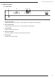
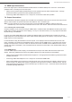
B-500-MTRX-230-8x8 Installation Manual 6. Device Layout 6.1. Front Panel 1 2 3 4 5 1. Power On/Off Switch Toggle Power from On to Stand-by. Can be disabled from Configuration Utility software. 2. Source Status LEDs Indicates that the selected source is on and transmitting an HDMI signal. 3. Output Display Displays the last output selected. 4. IR Receiver Window IR receiver for Matrix to capture commands sent by IR remote. 5. Input Display Displays the last input selected. Pg. 5 www.snapav.
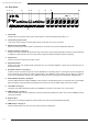
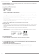
B-500-MTRX-230-8x8 Installation Manual 6.2. Rear Panel 1 2 3 4 5 6 7 8 9 10 Engineered in the USA Manufactured in Taiwan IR IN ALL IR OUT PWR 11 12 1. Power LED Indicates the current power status of the matrix switcher. Solid red indicates that power is on. 2. Latch-Locking Power Jack +24V 5A DC power supply connection with locking screw collar for secure connection. 3. RS-232 control port (DB9) Attach connection from control system or Windows PC for serial control of the B-500-MTRX-230-8x8.
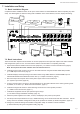
B-500-MTRX-230-8x8 Installation Manual 7. Installation and Setup 7.1. Basic Installation Diagram Complete the basic installation section to set up the matrix switcher for media distribution before completing any other setup. Use this diagram for reference during basic installation of the matrix switcher, sources, displays and wiring.
B-500-MTRX-230-8x8 Installation Manual 7.3. Installation Tips Following these tips during the installation process will help guarantee a successful installation. • Test every cable before use. Always test cables before use. Field-terminated cables should be checked for continuity after termination to be sure the connectors were installed correctly. • Label each cable as it is installed.
B-500-MTRX-230-8x8 Installation Manual 7.5. HDMI Input Connections Each of the eight inputs on the B-500-MTRX-230-8X8 utilizes a standard HDMI port for connection. Follow these guidelines when connecting sources to the inputs. • lways use the shortest cable possible between source equipment and the matrix switcher inputs. Use high A speed rated cables to guarantee the best possible performance. • Avoid using HDMI cable adapters in runs. Always run one unbroken cable when possible. 7.6.
B-500-MTRX-230-8x8 Installation Manual 7.6.3. HDBaseT Outputs Follow these guidelines when selecting and installing the HDBaseT cable, and then follow the instructions afterward to complete the connections for an output. 7.6.3.1. HDBaseT Wiring Recommendations Cable Type- Shielded or Unshielded Cat5e/6 • Cable Distance Limitations: Cat5e/ Cat6: Up to 200 ft Cat6a: Up to 230 ft • se at least Category 5e high-quality twisted pair solid conductor cable rated to no less than 350 Mhz bandwidth.
B-500-MTRX-230-8x8 Installation Manual 7.7. Matrix Control Connections All drivers, associated software and extra documentation is available on the B-500-MTRX-230-8X8 product page at www.SnapAV.com under the Support Tab. 7.7.1. IR Control The B-500-MTRX-230-8X8 can be controlled by IR from the front panel receiver or by attaching a mono cable from the control system flasher output to the “System IR In” port on the back of the matrix switcher. For the most reliable control, use the System IR In port.
B-500-MTRX-230-8x8 Installation Manual 7.8. IR Pass-Through Installation and Setup To utilize IR pass-through between a display location and the matrix switcher, install a B-500-RX-230-IR at the display and use HDBaseT for routing the signal. The matrix switcher and the matrix receiver are equipped with ports to allow commands to be sent to the display or from the display area. This section details the pinouts and correct use of the IR pass-through ports. 7.8.1.
B-500-MTRX-230-8x8 Installation Manual 7.9. B-500-RX-230-IR IR Connections The B-500-RX-230-IR IR ports are described below. Use the diagram for reference. 1 2 7.9.1. IR Receiver Attach an IR receiver to this port to capture IR commands in the room for pass-through for sources. This port will also send commands back to the matrix switcher for control of source selection in each zone. 12V DC (Sleeve) GND (Ring) IR Signal (Tip) IR Signal GND (Ground) +12V DC Tip Ring Sleeve 7.9.2.
B-500-MTRX-230-8x8 Installation Manual 7.10. IR Application Diagrams 7.10.1. IR Pass-Through from Control System IR Flasher Ethernet Connection IR Flasher Cat5e/6 RS232 RS232 Cable HDMI Source HDMI Source IR Outputs IR Inputs PLAY 3.
B-500-MTRX-230-8x8 Installation Manual 7.10.2.
B-500-MTRX-230-8x8 Installation Manual 8. EDID Configuration The displays used within an installation usually vary from room to room, and some may not support all resolutions available from a source. It is necessary to make sure sources will provide a video and audio format compatible with all connected displays programmed to use them. To accomplish this, the B-500-MTRX-230-8X8 includes built-in EDID management for each source input.
B-500-MTRX-230-8x8 Installation Manual 8.4. Embedded EDID COnfiguration In addition to the automatic configuration method, EDIDs in the B-500-MTRX-230-8X8 can be set to inputs manually by selecting an EDID from the embedded list (default EDIDs programmed into the matrix switcher). The matrix switcher contains eight ‘embedded’ EDIDs that may be assigned to inputs. These EDIDs define groups of video and audio capabilities that are useful for configuring sources in most systems. 8.4.1.
B-500-MTRX-230-8x8 Installation Manual 8.4.2. How to Set Embedded EDID for a Single Input Example: Input =1 Embedded EDID=4 Display Readout (Example) 3. Press INPUT E4A 4A 4. Press Number Key (1-8) to select the Input to which the EDID is applied 41 1. Press DEFAULT 2. Press Number Key (1-8) to select one Embedded EDID -FF 5. Press ENTER (success) (fail) 8.4.3. How to Set Embedded EDID for All Inputs Example: Input =1 Embedded EDID=4 Display Readout (Example) EA4A -- (success) FF (fail) 1.
B-500-MTRX-230-8x8 Installation Manual 8.5.2. How to Learn EDID to All Input Example: Input=All EDID Learned from Output 4 Display Readout (Example) L.-. L- 1. Press LEARN 2. Press OUTPUT 3. Press Number Key (1-8) to select the Output the EDID is learned from 4 -FF 4. Press ENTER (success) (fail) 8.6.
B-500-MTRX-230-8x8 Installation Manual 9. Advanced Setup Using the Configuration Utility There are several setup options available that can only be modified using the matrix switcher Configuration Utility. These items are defaulted to the most common settings that should work in most installations. The Configuration Utility and manual are available for download on the Support Tab of the B-500-MTRX-230-8X8 product page at www.SnapAV.com.
B-500-MTRX-230-8x8 Installation Manual 11. Operation and Control During setup and testing, use the included IR remote to control the matrix switcher. After setup is complete, a control method should have been setup and programmed as described in Section 7.7. Matrix Control Connections for regular operation. 11.1. IR Remote This section describes the correct button-push sequences to perform regular operations with the IR remote.
B-500-MTRX-230-8x8 Installation Manual Input to All Outputs Example: Output=All Input=4 Display Readout (Example) -AAA4 44 1. Press OUTPUT 2. Press ALL to select all Outputs 3. Press INPUT 4. Press Number Key (1-8) to select Input 6. Press ENTER 11.1.2. Turn Off (Mute) Outputs Mute one Output Example: Output=1 Display Readout (Example) 4. Press ENTER -110 10 Mute All Outputs Display Readout (Example) 1. Press OUTPUT -AA0 40 1. Press OUTPUT 2. Press Number Key (1-8) to select Output 3.
B-500-MTRX-230-8x8 Installation Manual 11.1.4. Resetting to Factory Defaults This procedure resets the B-500-HDMATRIX to factory defaults: • EDIDs - 1080p Stereo (embedded EDID 2) • I/O - All Outputs set to Input 1 • 1CAT EDIDs cleared, DHCP - Enabled. Reset Factory Defaults 1. Press DEFAULT 2. Press DEFAULT 3. Press DEFAULT 4. Press DEFAULT 5. Press ENTER Display Readout (Example) E--DD D- Note: R esetting factory defaults can take up to 2 minutes to complete.
B-500-MTRX-230-8x8 Installation Manual 12. Troubleshooting If issues arise during installation or testing of the B-500-MTRX-230-8X8, follow these guidelines to troubleshoot. Use the System Layout chart on the next page to record a description of each part of the system. If a problem cannot be solved using the methods listed here, fill out the System Layout Chart as completely as possible and contact Binary Tech Support for assistance at (866) 838-5052. 12.1.
B-500-MTRX-230-8x8 Installation Manual 12.4. Audio Issues If a display on an output using 2 channel stereo audio is switched to an input with an EDID set to surround sound audio format, audio at the display speakers may be garbled, missing pieces of the audio track, or muted altogether. This symptom indicates that the display cannot down-convert the audio stream from the source. To fix this issue, the source must be set to output only 2 channel stereo audio.
B-500-MTRX-230-8x8 Installation Manual 14. System Layout Chart Use this chart to identify the sources and displays attached to the system, and make any notes about each part. When completing the outputs chart, make sure to indicate whether an HDMI cable, B-500-RX-230-IR, or another brand HDBaseT receiver is being used to extend signal to the display, and indicate the approximate length of any cables.
B-500-MTRX-230-8x8 Installation Manual 15. Specifications TECHNICAL HDMI Compliance HDMI 3D HDCP Compliance Yes Video Bandwidth 6.75Gbps Resolution HDMI over UTP Transmission Cat5e/ Cat6 Cat6a 1080i / 720p 24-bit color 200ft 230ft Full HD 1080P 24-bit color 200ft 230ft Full HD 1080P 36-bit deep color 200ft 230ft Input TMDS Signal 1.
131112-1124 © 2013 Binary™