Installation Manual EA-AMP-12D-45A 45 Watt, Class D 12 Channel Amplifier
EA-AMP-12D-45A Installation Manual Important Safety Instructions Warning: To reduce the risk of fire or electric shock, do not expose this apparatus to rain or moisture. 1. Read these instructions. 2. Keep these instructions. 3. Heed all warnings. 4. Follow all instructions. 5. Do not use this apparatus near water. 6. Clean only with dry cloth. 7. Do not block any ventilation openings. Install in accordance with the manufacturer’s instructions. 8.
EA-AMP-12D-45A Installation Manual Table of Contents 1. Features 5 2. Package Contents 6 3. Recommended For Installation 6 3.1. Tools 6 3.2. Materials 6 3.3. Speaker Recommendation 6 4. Device Layout 7 4.1. Front Panel 7 4.2. Bottom 7 4.3. Rear Panel 8 5. System Design Considerations 9 5.1. Speaker Placement 9 5.2. Volume Control 9 5.2.1. No Inline Volume Controls 9 5.2.2. With Inline Volume Controls 9 5.3. Control Method 9 6. Installation and Setup 10 6.1.
EA-AMP-12D-45A Installation Manual Welcome to Episode Episode® is one of the most highly-regarded brands of audio products available today. We appreciate your business, and we stand committed to providing our customers with the highest degree of quality and service in the industry. Episode amplifiers are built on the latest digital technology and deliver efficient, clean power to every room.
EA-AMP-12D-45A Installation Manual 2. Package Contents (1) (1) (2) (4) (1) EA-AMP-12D-45A Installation Manual Rack Mounting Ears and Screws Removable Rack Feet and Screws Detachable IEC Power Cable 3. Recommended For Installation 3.1. Tools • #2 Philips Screwdriver • Wire Strippers 3.2. Materials • Speaker Wire Use high-quality, 2 or 4 conductor, 14-18 gauge (AWG) speaker wire. The higher the strand count, the better the sound quality will be.
EA-AMP-12D-45A Installation Manual 4. Device Layout Use this section to become familiar with the connections, controls and features of the EA-AMP-12D-45A amplifier. Refer to the page numbers in parentheses for more information on items regarding setup and operation. 4.1. Front Panel 1 2 1. Power Toggle power between On and Standby when the amplifier is in the “On” power mode. Color State Blue Power On, Normal Operation Red Standby 2.
EA-AMP-12D-45A Installation Manual 4.3. Rear Panel 3 1 2 4 5 6 7 Same for All Outputs 8 9 10 11 12 1. Global Input A RCA stereo line for source A input. 2. Global Input B RCA stereo line for source B input. 3. Level (Gain/Volume) Adjust the gain level of each output zone individually. (Counterclockwise for minimum; clockwise for maximum.) 4. Channel Input Selector Select the Global Input (A or B) or the local Line In for the output. 5.
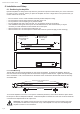
EA-AMP-12D-45A Installation Manual 5. System Design Considerations 5.1. Speaker Placement The EA-AMP-12D-45A amplifier output zones are arranged in pairs of left and right channels. Each pair can be bridged for one mono channel.
EA-AMP-12D-45A Installation Manual 6. Installation and Setup 6.1. Positioning the Amplifier Episode amplifiers are designed to help deliver a great audio experience that makes your music come alive for years to come. However, where you place the amplifier can have a large effect on the performance you receive and the life of the unit. • Be sure that the unit is in a well-ventilated area that provides adequate cooling. • Do not block the cooling vents located on both sides of the unit.
EA-AMP-12D-45A Installation Manual 6.2. Speaker Connections and Setup The EA-AMP-12D-45A has removable connectors to allow for the connection of two channels on each output zone (1 left and 1 right) or one bridged mono channel if more power is needed. Follow the directions below to properly connect speaker wiring. 6.2.1. Terminating Speaker Wire Connectors Each output zone of the EA-AMP-12D-45A utilizes a 4-pole set screw type connector for speaker wire connection. To terminate the connectors properly: 1.
EA-AMP-12D-45A Installation Manual 6.3. Source Connections and Input Setup 6.3.1. Input Selector Switch The EA-AMP-12D-45A has several options for attaching sources. Global inputs A and B can be used to route audio to any of the output zones, or a zone may be fed individually by its Local input. Settings and connections vary based on the output settings used. Each output zone (1-6) has its own switch to control the input used for the zone.
EA-AMP-12D-45A Installation Manual 6.4. Amplifier Power Control 6.4.1. Master Power Switch The master power toggle switch at the back of the unit controls the main power. If this is turned off the amplifier will not respond to any control method. This switch should be left in the ON position after installation and setup is finished unless the amplifier will not be used for an extended period of time or is being serviced. For everyday use, decide on one of the options below.
EA-AMP-12D-45A Installation Manual 6.5. Zone Volume Calibration Follow these directions to calibrate the LEVEL setting in relation to the source input volume and inline volume control level (if applicable) for the best sounding and most reliable installation. 1. Connect all speaker and audio source wiring and configure the amplifier. Connect power to the amplifier but leave it turned Off at the Master Power Switch. 2. (If applicable) Set all volume controls to their maximum volume setting. 3.
EA-AMP-12D-45A Installation Manual Applications Overview 6.6. Multi-Room Audio with Dedicated Sources Analog Out L Blu-ray Player Zone 2 Out R L R Input 1 AV Receiver Streaming Music Player Cable Box Input 2 Input 3 AppleTV R+ R- L- L+ Room 1 Room 2 R+ R- L- L+ R+ R- L- L+ Room 3 R+ R- L- L+ Room 4 R+ R- L- L+ R+ R- L- L+ Back Patio (Zone 5 & 6 Bridged) The diagram above illustrates the basic setup of a multi-room audio system with dedicated source inputs.
EA-AMP-12D-45A Installation Manual 6.7.
EA-AMP-12D-45A Installation Manual 7. Specifications Continuous Power Output (All Channels) 45 watts RMS at 4 ohms 30 watts RMS at 8 ohms Bridged Power Output (All Channels) 90 Watts per channel RMS at 8 ohms Note: Maintain 8 ohm minimum when using bridge mode Input Sensitivity 500mV Input Impedance 20,000 ohms AUTO ON (Audio Sense) Sensitivity 2.
EA-AMP-12D-45A Installation Manual 8. Troubleshooting Episode® amplifiers are designed to function trouble-free. Most problems that occur are due to simple issues. If you have trouble, please check the list of simple fixes below. If the problem persists, contact Episode® Technical Support at 1.866.838.5052. • Power cable to the amplifier is incorrectly connected or plugged into an outlet that does not have power. Check connections and verify power on the outlet.
EA-AMP-12D-45A Installation Manual 9. Warranty 2 Year Limited Warranty 2 year Episode® Amplifier products have a 2-Year Limited Warranty. This warranty includes parts and labor repairs on all components found to be defective in material or workmanship under normal conditions of use. This warranty shall not apply to products which have been abused, modified or disassembled.
130709-1345 © 2013 Episode®