Installation Manual EA-MINI-2D-35 EA-MINI-3D-35 35 Watts per Channel Digital Mini-Amplifier
EA-MINI-XD-35 Installation Manual 1. Important Safety Instructions Warning: To reduce the risk of fire or electric shock, do not expose this apparatus to rain or moisture. Do not remove cover. No user serviceable parts inside. Refer servicing to qualified service personnel. 1. Read and follow all instructions and warnings in this manual. Keep for future reference. 2. Do not use this apparatus near water. 3. Clean only with a dry cloth. 4. Do not block any ventilation openings.
EA-MINI-XD-35 Installation Manual Table of Contents 1. 2. 3. 4. 5. Important Safety Instructions Welcome to Episode® Features Package Contents Installation Recommendations 5.1. Tools 5.2. Cables and Wiring 5.3. Speakers 5.4. Subwoofer 5.5. IR Control 6. Device Layout 6.1. EA-MINI-2D-35 6.2. EA-MINI-3D-35 6.3. Layout Description 7. Installation 8. Positioning the Amplifier 8.1.1. Vertical Mounting (Walls or Enclosures) 8.1.2. Horizontal Placement 9.
EA-MINI-XD-35 Installation Manual 2. Welcome to Episode® Episode® is one of the most highly-regarded brands of audio products available today. We appreciate your business, and we stand committed to providing our customers with the highest degree of quality and service in the industry. Episode Mini amplifiers are built on the latest digital technology and were designed to deliver efficient, clean power to a soundbar or stereo speaker zone from either of two source inputs.
EA-MINI-XD-35 Installation Manual 5. Installation Recommendations 5.1. • 5.2. Tools #2 Philips Screwdriver • Wire Strippers Cables and Wiring • Speaker Wire Use high-quality, 2 or 4-conductor, 14-18 gauge (AWG) speaker wire. The higher the strand count, the better the sound quality will be. • RCA Input and Subwoofer Output Cables Use high-quality pre- or field-terminated RCA cables and connectors rated at 75 Ohms impedance. Binary™ cables and connectors are recommended.
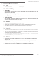
EA-MINI-XD-35 Installation Manual 6. Device Layout 6.1. EA-MINI-2D-35 1 2 3 4 5 6 UP CONTROL SWITCH POSITION IR RECEIVER DOWN 1 ANALOG IN IR OUT RUN MONO FULL IN 1 LEARN STEREO HP 60Hz IN 2 2 3 4 5 1 SUB OUT 100-240V~50/60Hz 1.6A SPEAKER OUTPUTS R+ R- L+ L- +5V GND STATUS LEFT 1 2 3 4 5 SWITCHES RIGHT RESET IR IN 7 6.2.
EA-MINI-XD-35 Installation Manual 6.3. Layout Description 1. Power Connector Attach the included IEC cable to this port for power. 2. IR Out 3.5mm mono mini port to send IR commands from IR IN to other equipment. 3. IR In 3.5mm stereo mini connection for attaching an IR receiver or an IR flasher output from other equipment. Commands for the amplifier are captured via this input. All IR signals pass through to the IR OUT port. 4.
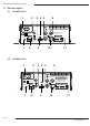
EA-MINI-XD-35 Installation Manual 7. Installation 256 Secondary Source UP CONTROL SWITCH POSITION DOWN 1 ANALOG IN IR OUT ES-SUB-WIRELESS Transmitter Toslink In RCA Left/Right In RUN IR RECEIVER LEARN 1 2 4 5 SUB OUT 100-240V~50/60Hz 1.
EA-MINI-XD-35 Installation Manual 8. Positioning the Amplifier 8.1.1. Vertical Mounting (Walls or Enclosures) • The amplifier may be mounted on any surface using fasteners suited for the surface material (not included). • The included module mounting pins may be used to secure the amplifier inside structured wiring enclosures. • The included rubber feet can be attached to dampen vibrations if needed. 8.1.2.
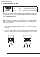
TUS 4 5 CHES EA-MINI-XD-35 Installation Manual 9. Speaker Connections and Setup 9.1.1. Stereo/Mono Dip Switch (Switch 3) Position Output Mode Descrpition Up Mono All speakers play the same mixed audio Down Stereo Each speaker plays its own audio channel 1 2 13 24 35 4 5 SWITCHES SWITCHES Set the output from the speakers to be mono or stereo format. Use mono for applications where left and right can’t be balanced.
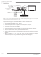
EA-MINI-XD-35 Installation Manual 10. Input Connections and Setup 10.1.1. RCA Input 1 (Left and Right Stereo) Connect a source using left and right analog RCA cables. 10.1.2. Toslink Input 2 Connect a source using a Toslink optical audio cable. No surround sound formats can be converted by the amplifier. Set source to output only 2-channel PCM stereo. Note: The EA-MINI-3D-35 will mix the signal from left and right channel inputs together to output to center channel. 10.1.3.
EA-MINI-XD-35 Installation Manual 11. IR Connections and Setup 11.1. IR Connections and Controls IR In Port Connect an IR Receiver or a 3.5mm mono mini cable to this port to input IR commands for amplifier control. Be sure to set the IR Receive/Control dip switch correctly to configure the port for the desired pinout. IR Receive/Control Dip Switch Controls the pinout of the IR In port to provide power for an IR Receiver if needed.
EA-MINI-XD-35 Installation Manual 11.2.2. IR Control with Programmed Commands For IR codes to be programmed into a control system or remote, visit the product page for the EA-MINIXD-35 at www.SnapAV.com to download. Follow the control system manufacturer instructions to configure commands for use. 11.2.3. IR Learning IR Learning allows control of the amplifier using the remote for a display or any other remote on a job.
EA-MINI-XD-35 Installation Manual 11.3. IR Application Diagrams 11.3.1. Using In-Room IR Receiver and Remote To control the amplifier with an in-room IR remote (commands transmit directly from the remote): 1. Set dip switch 1 to the DOWN position. 2. Connect the IR Receiver to the IR In port. 3. Position the receiver so that commands are received reliably.
EA-MINI-XD-35 Installation Manual 12. Sound Calibration The EA-MINI-XD-35 features built-in digital sound processing to allow for the dealer or end user to fine-tune settings such as balance, subwoofer volume, and treble and bass equalization. Additionally, there are three preset options optimized for movie, music, and vocal audio. To change DSP settings, use the accessory remote or a programmed universal remote. The commands for DSP cannot be set up via IR learning. 12.1.
EA-MINI-XD-35 Installation Manual 13. Troubleshooting • Power cable to the amplifier is incorrectly connected or plugged into an outlet that does not have power. Check connections and verify power on the outlet. No audio • Audio cable to the source component is not connected properly, is connected to the incorrect input, or the cable is defective. • Set the input volume level higher. Hum or buzzing sound is heard Amplifier will not turn on • Check audio output of source for correct setup.
EA-MINI-XD-35 Installation Manual 14. Specifications 26 watts RMS at 8 ohms Continuous Power Output (Both channels driven) 35 watts RMS at 6 ohms 35 watts RMS at 4 ohms 4 ohms: 420mV Analog (Gain: 29dB) 6 ohms: 500mV 8 ohms: 500mV Input Sensitivity 4 ohms: -20dBFS Digital (Gain: 40dB) (Vrms/FS) 6 ohms: -18dBFS 8 ohms: -18dBFS Input Impedance RCA Analog input: 20K ohms Auto On (Audio Sense) Sensitivity (RCA input) 2.
EA-MINI-XD-35 Installation Manual 15. Dimensions 5.40in. (Without mounting ears) 2.00in. EA-MINI-3D-35 6.50in. (With mounting ears) Pg. 18 6.90in.
EA-MINI-XD-35 Installation Manual 16. Warranty 2 year 2 Year Limited Warranty Episode® Amplifier Products have a 2-Year Limited Warranty. This warranty includes parts and labor repairs on all components found to be defective in material or workmanship under normal conditions of use. This warranty shall not apply to products which have been abused, modified or disassembled.
130829-0950 © 2013 Episode®