MINI HAWK III REVOLUTION MONTAGE ANLEITUNG INSTRUCTIONS MANUAL MANUEL D‘UTILISATION
DE WARNUNGEN ACHTUNG: Lesen Sie die GESAMTE Bedienungsanleitung, um sich vor Inbetriebnahme mit den Funktionen des Produkts vertraut zu machen. Eine nicht ordnungsgemäße Bedienung des Produkts kann das Produkt und persönliches Eigentum schädigen und schwere Verletzungen verursachen. Dies ist ein hoch entwickeltes Produkt für den Hobbygebrauch. Es muss mit Vorsicht und Umsicht bedient werden und erfordert einige mechanische Grundfähigkeiten.
DE TECHNISCHE DATEN Spannweite: 1300 mm (51 in) Länge: 940 mm (37 in) Tragflächeninhalt: 16,8 dm² (260 in²) Fluggewicht: 900 g Profil: MH-43 Motor: GTX-3534 (1200KV) Regler: 40 A Servo (Querruder): 2x Dymond DS 1660 MG Servo (Höhenruder): 1x Dymond DS 1660 MG Propeller: CamCarbon 10x7“ Spinner: Reisenauer Turbo 35 mm + 37/4 Mittelteil ARF PNP P 3S LiPo-Akku 2200 - 2400 mAh X X P kompatibles LiPo-Ladegerät X X P Dymond Smart 40A Flugregler X X P Dymond GTX-3534 Motor X P 3x
DE VORWORT Herzlichen Glückwunsch zum Erwerb des MINI HAWK III. Wie der Name bereits verrät, handelt es sich bei dem MINI HAWK III um die mittlerweile dritte Version des beliebten Hotliners aus dem Hause Staufenbiel. Das Modell wurde im Vergleich zum Vorgänger an diversen Stellen im Rumpf mit CFK verstärkt; zudem verfügt es nun serienmäßig über Kühlungsschlitze. Für ein neutrales Flugverhalten bei hohen Geschwindigkeiten wurde die EWD auf 0° korrigiert.
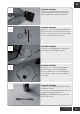
DE NUR ARF-VERSION: Entfernen Sie mit einem Fräser oder kleinen Seitenschneider zur leichteren Montage die beiden Haltelaschen am Höhenruderservo. 3 4 5 6 7 1,6 mm NUR ARF-VERSION: Stutzen Sie das Servohorn gemäß Abbildung. Bohren Sie das Loch auf 1,6mm auf. Stellen Sie das Servo mit einem Servotester auf Neutralposition und verschrauben Sie das Horn. NUR ARF-VERSION: Schleifen Sie die Auflagefläche im Rumpf nun auch mit grobem Schleifpapier gut an.
DE 8 9 10 6 NUR ARF-VERSION: Stecken Sie das Anlenkgestänge auf das Servohorn. NUR ARF-VERSION: Fädeln Sie das Servokabel und das Anlenkgestänge durch den Rumpf. Fixieren Sie das Servo im Rumpf zunächst vorläufig mit einer Montageklemme. Stellen Sie sicher, dass das Servohorn in Neutralposition steht. NUR ARF-VERSION: Montieren Sie nun das Höhenleitwerk und fädeln Sie das Anlenkgestänge in das GFKRuderhorn (äußeres Loch).
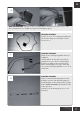
DE 11 Fixieren Sie die Schachtabdeckung mit TESA-Film oder UHU POR. 12 13 Verschrumpfen Sie die Motorkabel gemäß Abbildung. Fädeln Sie Motor und Regler durch den Rumpf, richten Sie den Motor so aus, dass die Motorkabel am Rumpfboden verlaufen. Verschrauben Sie den Motor (Loctite verwenden). Fixieren Sie den Schrumpfschlauch der Motorkabel mit Sekundenkleber am Rumpfboden, sodass die Kabel nicht an der Motorglocke schleifen können.
DE Montieren Sie Luftschraube und Spinner. 14 Überprüfen Sie auch bei der PNP Version den sicheren Sitz von Spinner, Luftschrauben und Spinnerkappe und ziehen Sie ggf. die Schrauben nach. Fixieren Sie Akku und Regler im Rumpf mit Klettstreifen. Der Empfänger wird hinten im Rumpf (hinter dem Akku) verbaut. 15 DIE TRAGFLÄCHE Die folgenden Beschreibungen beziehen sich auf beide Querruder, werden bildlich jedoch nur auf einer Seite gezeigt.
DE 19 NUR ARF-VERSION: Schleifen Sie den Schrumpfschlauch auf der Unterseite des Servos sowie den Schachtboden in der Tragfläche mit grobem Schleifpapier gut an. 20 21 22 NUR ARF-VERSION: Fertigen Sie zwei Servoverlängerungskabel mit jeweils 30cm Länge und verbinden Sie diese mit den Servos. NUR ARF-VERSION: Fädeln Sie die Verlängerungskabel durch die Tragfläche.
DE 23 24 25 NUR ARF-VERSION: Richten Sie das Servo durch Verschieben im Schacht aus, sodass das Querruder bei neutral stehendem Servohorn auch exakt neutral steht. Damit die Schachtabdeckung später passt, muss das Gestänge außerdem senkrecht zum Querruder stehen. Fixieren Sie das Servo nach dem Aussrichten mit einer Montageklemme. Begeben Sie anschließend mit einer Kanüle dünnflüssigen Sekundenkleber zwischen Servo und Tragfläche.
DE ABSCHLUSS Die Montagearbeiten sind nun abgeschlossen und es kann mit der Senderprogrammierung begonnen werden. Überprüfen Sie nochmals die Laufrichtung aller Servos. Bitte entnehmen Sie die Ruderausschläge sowie den genauen Schwerpunkt der Tabelle. Zum Landen sollten die Querruder als Bremsklappen hochgestellt werden. Je nach Ausschlag muss etwas Tiefenruder beigemischt werden. hält das Modell keine bösen Überraschungen parat.
DE KONFORMITÄTSERKLÄRUNG Horizon Hobby GmbH erklärt hiermit, dass dieses Produkt konform zu den essentiellen Anforderungen der EMC Direktive. Eine Kopie der Konformitätserklärung ist online unter folgender Adresse verfügbar : http://www.horizonhobby.com/content/support-render-compliance - UMWELTSCHUTZ-HINWEISE Dieses Produkt darf nicht mit anderem Abfall entsorgt werden.
DE www.staufenbiel-shop.com info@modellhobby.
EN WARNING WARNING: Read the ENTIRE instruction manual to become familiar with the features of the product before operating. Failure to operate the product correctly can result in damage to the product, personal property and cause serious injury. This is a sophisticated hobby product. It must be operated with caution and common sense and requires some basic mechanical ability. Failure to operate this product in a safe and responsible manner could result in injury or damage to the product or other property.
EN SPECIFICATIONS Wingspan: 1300 mm (51 in) Length: 940 mm (37 in) Wing area: 16,8 dm² (260 in²) Flying weight: 900 g Profil: MH-43 Motor: GTX-3534 (1200KV) ESC: 40 A Servo (Ailerons): 2x Dymond DS 1660 MG Servo (Elevator): 1x Dymond DS 1660 MG Propeller: CamCarbon 10x7“ Spinner: Reisenauer Turbo 35 mm ARF PNP P 3S LiPo-Pack 2200 - 2400 mAh X X P LiPo Charger X X P Dymond Smart 40A ESC X X P Dymond GTX-3534 Motor X P 3x Dymond DS 1660 MG Servos X P 35mm Spinner + Propel
EN PREFACE Congratulations on your purchase of the MINI HAWK III. As the name implies, the MINI HAWK III is the third version of Staufenbiel’s popular series of hotliners. In comparison to its predecessors, this model has additional CFRP reinforcements in various places on its fuselage as well as cooling vents that have become a new series standard. In addition, the EWD has been corrected to 0° for neutral flight behaviour at high speeds.
ARF VERSION ONLY: For an easier assembly, remove both retaining plates on the elevator servo with a milling cutter or a cable cutter. 3 4 5 6 7 1,6 mm EN ARF VERSION ONLY: Crop the servo horn according to the picture. Expand the hole to 1.6mm using a drill. With a servo tester, place the servo in a neutral position and screw in the horn. ARF VERSION ONLY: Then roughen the support surface in the fuselage with a large piece of coarse sandpaper.
EN 8 9 10 ARF VERSION ONLY: Put the linkage rod on the servo horn. ARF VERSION ONLY: Thread the servo cable and the linkage rod through the fuselage. Next, temporarily hold the servo in place in the fuselage with a mounting clamp. Make sure that the servo horn is in a neutral position. ARF VERSION ONLY: Now assemble the tailplane and thread the linkage rod through the GRP control horn (the outer hole).
EN 11 Hold the compartment cover in place with adhesive tape or UHU POR, a quick-setting adhesive. 12 13 Apply shrink sleeves to the motor cables according to the picture. Thread the motor and regulator through the fuselage, and adjust the motor so that the motor cables run along the bottom of the fuselage. Screw together the motor (apply Loctite). Attach the shrink sleeve on the motor cables to the bottom of the fuselage with superglue, so that the cables cannot grind against the motor flange.
EN Install the propeller and spinner. 14 Even with the PNP version you should then check that the spinner and propeller have been securely fastened so that you can tighten the screws if necessary. Secure the battery and the regulator in the fuselage with velcro strips. The receiver is to be installed at the back of the fuselage (behind the battery). 15 THE WING The following description pertains to both ailerons, however the picture illustrates only one side.
EN 19 ARF VERSION ONLY: Sand the shrink sleeve on the bottom side of the servo as well as the bottom of the compartment in the wing with coarse sanding paper. 20 21 22 ARF VERSION ONLY: Prepare two servo extension cables that are each 30cm long and connect them to the servos. ARF VERSION ONLY: Thread the extension cables through the wing. In order to make the assembly of the model easier, we recommend installing an additional plug-in connector with an MPX connector between the wing and the receiver.
EN 23 24 25 ARF VERSION ONLY: Shift the servo in the compartment so that when the servo horn is in a neutral position the aileron is also in a perfectly neutral position. In order to ensure that the compartment cover will fit, the rod has to be perpendicular to the aileron. After adjusting the servo to the correct position, fix it in place with a mounting clamp. Then using a cannula, pour liquid superglue between the servo and wing.
EN COMPLETION The model assembly is now complete and you can get started with the channel programming. Check the running direction of servos one more time. Please make note of the rudder deflections as well as the exact center of gravity in the table. For landing, the aileron should lifted as a brake flap. Now you can enjoy your first flight with your new MINI HAWK III. With the information contained within these instructions, this model holds no unpleasant surprises for you.
EN DECLARATION OF CONFIRMITY EU Compliance Statement: Horizon Hobby, LLC hereby declares that this product is in compliance with the essential requirements and other relevant provisions of the EMC Directive. A copy of the EU Declaration of Conformity is available online at: http://www.horizonhobby.com/content/support-render-compliance. - DISPOSAL OF WEEE BY USERS IN THE EU This Product must not be disposed of with other waste.
EN www.staufenbiel-shop.com info@modellhobby.
AVERTISSEMENT FR AVERTISSEMENT : lisez la TOTALITÉ du manuel d‘utilisation afin de vous vous familiariser avec les caractéristiques du produit avant de le faire fonctionner. Une utilisation incorrecte du produit peut entraîner sa détérioration, ainsi que des risques de dégâts matériels, voire de blessures graves. Ceci est un produit de loisirs sophistiqué. Il doit être manipulé avec prudence et bon sens et requiert des aptitudes de base en mécanique.
CARACTERISTIQUES Envergure : 1300 mm (51 in) Longeur : 940 mm (37 in) Surface l‘aile : 16,8 dm² (260 in²) Poids (prêt à voler) : 900 g Profil : MH-43 Moteur : GTX-3534 (1200KV) Variateur : 40 A Servo (Ailerons) : 2x Dymond DS 1660 MG Servo (Profondeur) : 1x Dymond DS 1660 MG Hélice : CamCarbon 10x7“ Cône : Reisenauer Turbo 35 mm FR ARF PNP P Accu LiPo 3S 2200 - 2400 mAh X X P Chargeur LiPo X X P Variateur Dymond Smart 40A X X P Moteur Dymond GTX-3534 X P 3x Dymond DS 1660
PRÉFACE FR Félicitations pour l‘acquisition de votre MINI HAWK III . Il s‘agit ici de la troisième version du très apprécié hotliner de Staufenbiel. Par rapport à son prédécesseur, le modèle a reçu des renforts en fibre de carbone, les ouïes d’aération sont déjà découpées et le calage de l‘aile à été modifié à 0° pour donner un comportement neutre en vol.
UNIQUEMENT SUR VERSION ARF : A l‘aide d‘une mini fraiseuse, supprimez les pattes de fixation du servo de profondeur. 3 FR 4 5 6 7 1,6 mm UNIQUEMENT SUR VERSION ARF : Raccourcissez le palonnier de servo de telle sorte que seul le trou le plus proche de l‘intérieur subsiste. Percez ce trou au diamètre 1,6mm, puis à l‘aide d‘un testeur de servos placez le servo au neutre et vissez le palonnier en place.
8 UNIQUEMENT SUR VERSION ARF : Insérez la chape de la commande dans le palonnier de servo. FR 9 10 30 UNIQUEMENT SUR VERSION ARF : Enfilez le câble du servo et la commande dans le fuselage. Fixez le Servo dans le fuselage provisoirement avec un serre-joint Assurez vous que le palonnier de servo se trouve en position neutre. UNIQUEMENT SUR VERSION ARF : Remontez maintenant le stabilisateur et enfilez la commande dans le dernier trou du guignol de profondeur.
11 FR Fixez le couvercle de trappe de servo à l‘aide de ruban adhésif. 12 13 Mettez en place de la gaine thermo sur les câbles du moteur comme illustré. Enfilez le moteur et régulateur par l‘avant, orientez le moteur afin que les câbles de moteur courent sur le fond du fuselage Vissez le moteur en utilisant du Loctite frein filet . Coller les câbles avec de la colle cyano sur le fond du fuselage si bien que les câbles ne puissent frotter sur le moteur à cage tournante..
Procédez au montage du cône et de l‘hélice. Sur la version PNP, vérifiez la bonne fixation du plateau et du cône d‘hélice ainsi que des pales repliables. Profitez en pour vérifier également le bon serrage des vis. 14 FR Pour fixer l‘accu et le variateur, une bande de Velcro double face apposée dans le fond du fuselage suffit amplement. Le récepteur est fixé derrière l‘accu. 15 LES AILES Les explications qui suivent concernent les deux ailerons, même si l‘illustration ne montre qu‘un seul côté.
19 FR UNIQUEMENT SUR VERSION ARF : Rendrez rugueuse la gaine thermo en la ponçant sur tous ses côtés. 20 21 22 UNIQUEMENT SUR VERSION ARF : Fabriquez deux rallonges de servos d‘une longueur de 30 cm chacune et reliez les aux servos. Nous conseillons l‘emploi de ruban adhésif ou d‘un clip de sécurité. UNIQUEMENT SUR VERSION ARF : Enfilez les câbles-rallonges dans les ailes. Afin de simplifier le montage du modèle, nous conseillons d’utiliser une prise multiplex entre l‘aile et le récepteur.
23 FR 24 25 UNIQUEMENT SUR VERSION ARF : Collez les servos en place avec le palonnier dans l‘axe du guignol. Respectez impérativement l‘angle de 90° avec la gouverne mobile. Vous pourrez utilisez la colle époxy ou la cyano. Montez ensuite les commandes et réglez celles ci afin que la gouverne soit au neutre. UNIQUEMENT SUR VERSION ARF : Montez en place les caches de servos à l‘aide de colle UHU Por, ce qui permettra si besoin par la suite de les démonter simplement et sans dégâts sur l‘entoilage.
FINITIONS Les travaux de montage sont maintenant achevés et l‘on peut commencer la programmation de la radiocommande. Vérifiez une fois encore le sens de fonctionnement de tous les servos. Pour l’atterrissage, il est conseillé d‘utiliser les ailerons comme aérofreins en position relevée. Dans ce cas il est nécessaire de programmer un mixage à piquer d‘environ 1 mm. Veuillez prendre en compte le bon centrage et trouver les débattements conseillés ci-dessous.
DECLARATION DE CONFORMITÉ Ce produit respecte les critères de sécurité essentiels déterminés dans la directive du Conseil de l‘ Union européenne relative à l‘harmonisation des dispositions légales des États membres sur la compatibilité électromagnétique (2004/108/CE). Une déclaration de conformité est disponible. FR PROTECTION DE L‘ENVIRONNEMENT de sa durée de vie. Il doit être déposé dans un point de collecte pour le recyclage d‘appareils électriques et électroniques.
FR www.staufenbiel-shop.com info@modellhobby.