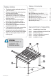
BR FA IC 3 Pergola PR100N1 Assembly Instructions ’6” 11 0cm 35 7’9” 235cm 11 35 ’6” 0cm 10 32 ’6” 0cm Systems Trading Corporation www.stcny.
Introduction Thank you for purchasing the Pergola PR100N1. When properly assembled and maintained, this pergola will provide many years of enjoyment! These instructions include helpful hints and important information needed to safely assemble and properly maintain the pergola. Please read these instructions completely before you begin. Our patented pergola has been designed for easy assembly. All steps can be completed by a team of three people. The assembly should take about two hours.
Table of Contents Safety Advice • • • • • • • • • • The pergola must be positioned and fixed on a flat level surface. Dispose of all plastic bags safely. Keep them out of the reach of children. Keep children and pets away from the assembly area until the work is completed. Always wear shoes, gloves and safety goggles when working. Take special care not to touch overhead power lines with the aluminium profiles. Do not attempt to assemble the pergola in windy or wet conditions.
No. Part Qty Step No. Part Qty Step 17 1 6 26 14 3 18 7 6 26A 7 5 19 7 6 27 1 20 2 6 28 16 4 We included some extra screws and bolts for your convenience. 21 16 4 24 2,5 94 1,2 3,5 24 14 6 25 15 6 22 Screw ø 1/4*x 75mm 23 Screw ø 1/4”x 15mm Screw ø 4*12mm www.stcny.
STEP 1 Assembling the Corner Posts Place all the parts on a level surface. Make sure the pieces are in the correct positions before assembling. Carefully follow the order of assembly to ensure an easy installation. Wear proper safety gear including work shoes, gloves and goggles. Components Corner profile (1) Roof connector (10) x4 1.A x4 Support plate (8) Support frame (9) x4 Screw (23) x4 x 24 Place corner profiles (1) parallel to each other the ground.
1.B Slide support frames (9) over lower end of corner profiles (1). Align pre-drilled screw holes in corner profiles (1) with screw holes in support plate (8). Attach support plates (8) to corner profiles (1) as shown, using two screws (23) for each plate. 9 9 1 1 9 1 23 8 23 8 Leave support frames (9) about 10”over lower end of corner profiles (1) until step 4 (Securing the pergola to the ground) 1 8 Create 4 corner posts x4 1 1 1 1 www.stcny.
STEP 2 Attaching the Beams to the Corner Posts Components Screw (23) Short Beam (5) x2 Long Beam (4) Beam connector (11) x2 x2 2.A Post Connector (15) x4 x 28 Magnet (16) Screw (22) x2 Insert beam connector (11) into hollow ends of one long beam (4) and one short beam (5) as shown. Attach with four screws (23) on side. x8 5 11 5 4 4 2.B 23 Attach magnet (16) to side of long beam (4) as shown. Attach with two screws (23). Repeat steps 2A and 2B to create two sets of long beams.
2.C Place one long beam (4,5) into cut-out on corner posts (1,10) as shown. Attach post connector (15) using two screws (22) through pre-drilled holes in long beam (4,5). Attach post connector to post using four screws (23). Do not tighten the screws, you will tighten them in STEP 3. 1 15 5 1 4 15 1 5 5 1 15 15 Repeat step 2C to create two sets. x2 www.stcny.
STEP 3 Building the Basic Frame IMPORTANT: You need at least 3 people to complete this step! Components Short Beam with track (7) Long Beam with track (6) Beam connector (12) x2 x2 x2 Screw (23) Canopy loops (26) x 16 x 14 3.A Insert beam connectors (12) into long beams with track (6) as shown and fasten using two screws (23) each. 12 23 12 6 6 Insert long beams with track (6) through post connectors (15) on top of posts, align screw holes and fasten using two screws (23) each.
3.C Using at least 3 people, lift frame sets and slide beam connectors (12) on long beams with track (6) into short beams with track (7) as shown. 7 12 6 7 12 6 Making sure to support the frame properly, fasten using screws (23). 4 7 5 6 6 7 5 23 4 7 6 IMPORTANT: After this step you should place the pergola frame in its desired location. Make sure all corners are squared at 90 degrees. www.stcny.
STEP 4 Securing the Pergola to the Ground Fasten the pergola frame to the ground, using four spikes (21) for each support plate. Lower support frames (9) to cover support plates (8). Components 1 9 1 Ground spike (21) x 16 21 8 8 Optional Securing the Pergola to a Concrete Floor or Wood Deck Concrete Floor: 1. Using a concrete drill, drill holes into the concrete floor, corresponding to the holes in support plates (8). 2. Insert concrete bolts into the holes and hammer into place, using a mallet.
STEP 5 Installing the Roof Beams ATTENTION: DO NOT ATTEMPT TO ASSEMBLE THIS ALONE ! Components Long Beam with track (6A) Short Beam with track (7A) Beam connector (12) Short Beam (3) Beam connector (11) x1 x1 Long Beam (2) x4 x4 x1 x4 Canopy loops (26A) Screw (23) x7 x 26 Screw (22) Roof connector (13) x 16 x2 5.A Insert beam connector (12) into long beam with track (6A) as shown and fasten using two screws (23).
5.B Insert beam connector (11) into beams (2) and (3) as shown and fasten using four screws (23). 2 11 3 2 3 Create four sets. 3 2 5.C 23 Attach beam with track (6A,7A) to roof beams (4,5) using roof connector (13) and fasten with three screws (23) on each side. Make sure to install the beam (6A,7A) exactly as shown. 7 6A 23 4 6 5 6A 4 7 7A 5 6 4 www.stcny.
5.D Attach beams (2,3) to roof beams (4,5) using two long screws (22) on each side. 22 3 4/5 7 4 3 3 6A 6 3 2 2 7 7A 5 2 2 6 4 www.stcny.
STEP 6 Installing the Canopy Components Canopy Rod (18) x7 Screw (24) Canopy (17) x1 Canopy Rod (19) x7 6.A Canopy Cover (20) x2 Metal Cover Connector (14) x4 x 14 Screw (25) x 15 Insert canopy rods (19) into canopy rods (20) as shown and fasten with screws (25). Create 7 sets. 18 19 18 19 25 6.B Spread out the canopy (17) on an even flat surface. Insert one canopy rod (18/19) into the first “sleeve” in the canopy until it shows in the center opening. 18/19 17 www.stcny.
6.C With the help of two people, pass the canopy rod (18/19) through the first canopy loop (26A) in beam with track (6A/7A) as shown. Continue sliding the rod through the canopy sleeve until it emerges at the other end. 17 18/19 17 26A 6A/7A 18/19 6.D Fasten the canopy rod (18/19) at each end to canopy loops (26) in beams with track (6/7) using screws (24). Repeat steps 6C/6D with all seven canopy rods (18/19). Use the attached handles to open and close the canopy.
6.E Slide metal cover connectors (14) into “sleeves “ in canopy covers (20). Fasten canopy covers (20) to the roof beams (6/7) with using screws (25) as shown. 25 20 20 14 6/7 6/7 20 6/7 20 www.stcny.
Enjoy your completed Pergola ! www.stcny.
BR FA IC 3 Pergola PR100N1 Assembly Instructions WARRANTY: Warranty covers damage due to manufacturing defects only. Warranty does not cover weather inflicted damage (Force Majeure) and/or damages caused by not following assembly instructions and adhering to warnings in manual. EasyGrow 8’x 12’ Greenhouse Systems Trading Corporation www.stcny.