OPERATION & INSTRUCTION MANUAL (6kW, 9kW & 12kW Steam Generator & DeLuxe Control Panel) Mandatory Reading Installation Updates- Page 4 Parts Request Info- Page 22 Note: SAVE SALES RECEIPT for proof of purchase/warranty
Table of Contents Read Me First .................................................................................................................... 1 Safety Warnings ................................................................................................................. 2 Safety Warnings In French ................................................................................................. 3 Mandatory Reading .....................................................................................
READ ME FIRST 1. Verify the parts checklist to ensure that all necessary parts have been received. 2. DO NOT TWIST THE PLUGS together when connecting the keypad and/or the keypad extension wire to the steam generator cable. Twisting will damage the pins and it is not covered under the warranty. 3. Keypad box contains: a. Keypad b. Steam head c. Escutcheon (temperature detector foundation) 4. Light kits are available for the GS08 Steam Generators. White lights and chromotherapy lights are available.
WARNING! To reduce the risk of injury, do not permit children to use this product unless they are closely supervised at all times. WARNING! To reduce the risk of injury: a. The wet surfaces of steam enclosures may be slippery. Use care when entering or leaving. b. The steam head is hot. Do not touch the steam head and avoid the steam near the steam head. c.
DANGER! Afin de réduire les risque de blessures, ne jamais autoriser des enfants à utiliser ce appariel, sauf s’ils sont étroitement surveillés, à tout moment DANGER! a) Les cabines où de la vapeur est introduite peuvent comporter des surfaces humides et donc glissantes. La plus grande prudence est de rigueur au moment où l’utilisateur pénêtre, ou quitte la cabine b) La tête d’injection de la vapeur est à haute temperature; il faut veiller à ne pas entrer en contact avec cette tête d’injection.
MANDATORY READING INSTALLATION UPDATE BULLETIN INSTALLATION OF 9KW AND 12 KW STEAM GENERATORS When connecting the power supply for the 9kW and 12kW steam generators, there may be some difficulty connecting the 8 and 6-gauge wires into the terminal block. In order to make these connections as easy as possible, you can remove steam generator wires from the terminal block and wire nut the wires directly to your power source. This will make the electrical connections easier.
Part 1: Steam Generator USER INSTRUCTIONS Attention: We are not responsible for the malfunction and damage from improper installation that does not comply with the user’s manual. 1. Make sure the model and the accessories are correct, including the voltage 220V input. 2. Make sure the steam power is matched with the dimensions of the steam room. Pay attention to the steam room's cubic feet measurements and construction materials. See below on how to choose your type of machine. 3.
SENSOR PROBE REMOVAL FOR DIRECT CLEANING Make sure the power is shut off at the circuit breaker. The water level sensor probe is located on top of the steam generator tank. You need to remove the cover of the steam generator, next locate the large transformer, near it should be a hole with three wires going into it and attached to tabs. That is the water level sensor. Older units have a ceramic sensor. The newer units have a two-piece sensor, a nylon threaded ring and a red rubber center.
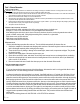
Attention: The steam generator (including the controller) is ETL approved. INSTALLATION DRAWING OF THE STEAM GENERATOR ! A tten tion : T h e d r a w i n g is o n ly fo r ex pla n a tio n . F or p r ac tic a l de s ig n o f s te am r o o m , p le a s e qu al ifie d C o n tr o l p an el c o n su lt d e s ig n e r, w ith ar c h i te ct o r b u il d e r.
WARNING! The steam nozzle and steam outlet are very hot! Avoid installing the steam nozzle near steam bathers. 1. Install the steam nozzle 6-12 inches above the ground. 2. The steam spray outlet should be installed face down. Wrap a few circles of Teflon tape around the threads of the steam pipe, install the steam nozzle and tighten with hands. DANGER! 1. Installer la tête d’injection de vapeur enter 15 et 30 cm au-dessus du sol.
BLUEPRINT FOR THE STEAM ENGINE 9 Rev. 8.
Attention: Keep the steam engine clean. Attention: To avoid damage to the equipment, do not connect power directly to the components. IMPORTANT: Each unit is provided with a pressure-release device (safety valve) to address overpressure due to inadvertent blockage of the output steam head or piping. ELECTRICAL REQUIREMENTS: Electricity supply circuitry: 1. Test the voltage of the electric supply and make sure that the steam engine is supplied with suitable electric power. 2.
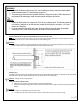
S L ig h t WIRING DIAGRAM 220-240V (1PH/2PH) B ro w n Red 6 & 9kW Steam Generators: Red B la c k Red Red Red B lue Red S Red G S 08-4.
NOTE: NOW AVAILABLE FOR THE GS08 STEAM GENERATORS LED Lighting Kits -White or Chromotherapy Lights Hole for light is 1 13/16in. Diameter of light is 2 3/16in. Length of light is 1 1/2in Drip Pan- 20x10x1 and weighs 3 lbs. *For pricing, please contact your place of purchase INSTALLATION OF THE TOP LIGHT Attention: 12V output port is available for 12V DC accessories (not included).
STEAM GENERATOR CONFIGURATION 2 1 3 4 5 6 7 8 9 Enclosure 7 Water drain valve Terminal block 2 Insulation bracket Circuit board 8 Subsidiary water tank Terminal block (pg 4) Fuse 3Steam Circuit outletboard 9FuseMain water tank Ground connector 4Pressure Steamrelease Outlet valve Heating Element Ground connector Relay valve) 5 (safety Pressure relief valve O Relays 221 F Hi-limit Water level sensor fill valve 6Water Water fill valve Water level sensor Transformer 221 F Hi-limit Insul
TROUBLE SHOOTING: Trouble Causes of Trouble Trouble-Shooting Method The machine does not start when power is supplied 1. The fuse is burned 2. The wire connection terminal is loose 3. Bad contact in the connection wire between the controller and the steam engine 1. Change the fuse (on the shell 0.8A/250V) 2. Plug-in the wire connection terminal 3. Make sure the steam engine and controller are in good contact. Check pins on controller cable GFCI switch breaks automatically 1.
Instructions for Resetting the manual hi-limit switches If the unit fills with water but does not produce steam, the issue may not be the heating element. 1. Shut off the power to the unit at the breaker. 2. Remove the top of the steam generator and make sure the power connections are tight. 3. There is an update that allows you to disconnect the wires from the terminal block and wire nut them together.
PART 2: CONTROL PANEL Cleaning Instructions 1.Use soft cloth with a little soap water to clean the controller. 2.Do not use abrasive cleaning tools or material. Safety and operation information Warning: If the installation and operation instructions are not read or understood, do not install or use, to prevent serious damage or injury. Install the controller based on the installation instructions, otherwise, the temperature in the steam room will be too high or will not heat properly.
Blueprint for the control panel • Complete set including: • Control panel • Temperature sensor and holder • User manual • Middle cable between dual panels (6.5 feet) Installation instruction of controller Important Before installing the controller, make sure the steam generator is shut off otherwise the controller may not operate properly or be damaged. Step One: The controller is designed to be installed in the steam room. Points to consider: 1. 4-5 feet from the ground or a convenient height. 2.
Step Five: Temperature detector installation 1. The position of the temperature detector should be about head high while sitting and as far away as possible from the steam head. Avoid installing near the steam outlet or room door. 2. As shown in Fig. 1, drill a small hole of 3/8in. in the selected position. 3. Apply a circle of silicone along the edge of the back of the detector foundation (as shown in Fig 2) 4. Use a lock nut to lock detector foundation. (as shown in Fig .2) 5.
Controller function instruction Attention: Avoid bending the pins inside the cable connection the control panel and steam generator. Make sure the arrows on the male and female ends are lined up as illustrated below. Keypad operation The blue ring around the fly shuttle indicates the unit is in standby mode and ready for operation (8). Press the on/off button to start the operation of the generator. (1) Note - If the Steam Light (9) starts blinking, it means there is no water coming to the generator.
The unit will display the default time (6) and ambient temperature (5). To find out the default temperature press the temperature adjustment button (4). The unit will fill with water and after a few minutes begin to produce steam Once the unit has been shut off either by the time setting or manually pressing the on/off button (1), the automatic drain function of the generator will engage after about 10 minutes.
Optional- Dual Keypad System has the same main control panel and subpanel. The subpanel does not include steam control cable and external temp sensor. Functions on the main panel and subpanel are the same. Schematic 21 Rev. 8.
TO EXPEDITE PARTS REQUEST Please visit homewardbath.com/support If you require additional assistance, call 866-783-2661. WARRANTY INFORMATION & REGISTRATION Please visit our website: homewardbath.com/warranty-registration Registration must be completed within 45 days of receipt to be valid. A full description of the warranty is available on the Homeward Bath website. 22 Rev. 8.
NOTES: 23 Rev. 8.