
User manual

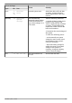
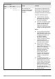
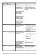
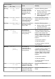
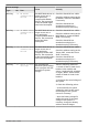

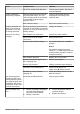
Table Of Contents
- 1 General information
- 2 Quick guide
- 3 Overview
- 4 Installation of the base system
- 5 Initial commissioning of the base system
- 6 Installation and initial commissioning of optional components
- 6.1 Commissioning the SD card (MPPT 6000-M only)
- 6.2 AUX 1,2,3 relay output connection (MPPT 6000-M only)
- 6.3 AUX IO remote control input connection (MPPT 6000-M only)
- 6.4 PA TS-S external temperature sensor connection
- 6.5 StecaLink slave connection
- 6.6 StecaLink master connection (MPPT 6000-M only)
- 6.7 UART/RS-232 interface connection (MPPT 6000-M only)
- 6.8 Redundancy function (MPPT 6000-S only)
- 6.9 Install cable strain relief
- 7 Display (layout, function, operation)
- 8 System functions
- 8.1 Protection functions
- 8.2 Battery type setting
- 8.3 Current limit system setting (MPPT 6000-M only)
- 8.4 Current limit device setting
- 8.5 Lead-acid battery system functions
- 8.5.1 Equalisation cycle mode
- 8.5.2 Battery control mode (MPPT 6000-M only)
- 8.5.3 Battery capacity test (MPPT 6000-M only)
- 8.5.4 Battery type
- 8.5.5 Battery capacity
- 8.5.6 Current limit system (MPPT 6000-M only)
- 8.5.7 Current limit device
- 8.5.8 Charge voltages
- 8.5.9 IUIA charge mode (MPPT 6000-M only)
- 8.5.10 Start boost charge
- 8.5.11 Battery temperature sensor
- 8.5.12 Cable compensation
- 8.5.13 PV string connection
- 8.5.14 Expert menu
- 8.6 Li-Ion battery system functions (MPPT 6000-M only)
- 8.7 NiCd battery system functions (MPPT 6000-M only)
- 8.8 StecaLink bus
- 8.9 Internal data logger
- 8.10 Clear log data
- 8.11 Clear event log
- 8.12 Factory settings
- 8.13 UART/RS-232 interface (MPPT 6000-M only)
- 8.14 Acoustic alarm
- 8.15 SD card (MPPT 6000-M only)
- 9 Control functions via AUX 1/2/3 (MPPT 6000-M only)
- 10 Troubleshooting
- 11 Maintenance, dismounting and disposal
- 12 Technical data
- 13 Guarantee conditions, exclusion of liability, contacts, notes

Event message
Cause Remedy
Type No. Text
Info -
Gateway
active
Gateway function active
on the StecaLink bus.
A StecaLink communication
device is directly accessing the
power unit data. If this function
was not intentionally triggered
then disconnect the device from
the StecaLink bus, switch it off
and on and then reconnect it to
the bus.
Info -
No SD card
MicroSD not present or
not recognised.
Correctly insert the SD card.
Format the SD card with a FAT16
file system, check for correct
functioning of the SD card on a
PC.
Info -
SD card full
No more parameter/data
files can be stored on the
microSD card.
Create free space on the SD card
by deleting old files or insert a
new empty SD card. Format the
SD card with the FAT16 file
system.
Info -
Settings
incompatible
Incompatible settings are
present, the contents of
the Master.ini parameter
file are not compatible
with the valid setting
ranges of the device.
Save the parameter file of the
device onto the microSD card.
Info -
File not
found
Master.ini parameter file
could not be found on
the microSD card. The
parameter file could not
be loaded.
Save the parameter file on the SD
card again.
10.3 Errors without event messages
The causes of the following errors cannot be controlled by the device. Therefore the device does not
display an event message when one of these errors occurs.
Error Possible cause Solution
No display. Battery voltage too low. Pre-charge the battery.
External fuse/circuit breaker for the
battery has blown/triggered.
Replace the external battery fuse
for the battery or reset the circuit
breaker.
Battery is not connected. 1. Unclamp all connections.
2. Connect a (new) battery with the
correct polarity.
3. Reconnect the solar module and
loads.
Battery is defective.
756.404 | Z01 | 16.06
118