
User manual
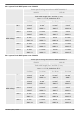
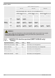
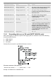
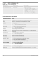
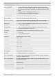
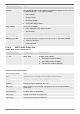
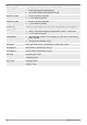
Table Of Contents
- 1 General information
- 2 Quick guide
- 3 Overview
- 4 Installation of the base system
- 5 Initial commissioning of the base system
- 6 Installation and initial commissioning of optional components
- 6.1 Commissioning the SD card (MPPT 6000-M only)
- 6.2 AUX 1,2,3 relay output connection (MPPT 6000-M only)
- 6.3 AUX IO remote control input connection (MPPT 6000-M only)
- 6.4 PA TS-S external temperature sensor connection
- 6.5 StecaLink slave connection
- 6.6 StecaLink master connection (MPPT 6000-M only)
- 6.7 UART/RS-232 interface connection (MPPT 6000-M only)
- 6.8 Redundancy function (MPPT 6000-S only)
- 6.9 Install cable strain relief
- 7 Display (layout, function, operation)
- 8 System functions
- 8.1 Protection functions
- 8.2 Battery type setting
- 8.3 Current limit system setting (MPPT 6000-M only)
- 8.4 Current limit device setting
- 8.5 Lead-acid battery system functions
- 8.5.1 Equalisation cycle mode
- 8.5.2 Battery control mode (MPPT 6000-M only)
- 8.5.3 Battery capacity test (MPPT 6000-M only)
- 8.5.4 Battery type
- 8.5.5 Battery capacity
- 8.5.6 Current limit system (MPPT 6000-M only)
- 8.5.7 Current limit device
- 8.5.8 Charge voltages
- 8.5.9 IUIA charge mode (MPPT 6000-M only)
- 8.5.10 Start boost charge
- 8.5.11 Battery temperature sensor
- 8.5.12 Cable compensation
- 8.5.13 PV string connection
- 8.5.14 Expert menu
- 8.6 Li-Ion battery system functions (MPPT 6000-M only)
- 8.7 NiCd battery system functions (MPPT 6000-M only)
- 8.8 StecaLink bus
- 8.9 Internal data logger
- 8.10 Clear log data
- 8.11 Clear event log
- 8.12 Factory settings
- 8.13 UART/RS-232 interface (MPPT 6000-M only)
- 8.14 Acoustic alarm
- 8.15 SD card (MPPT 6000-M only)
- 9 Control functions via AUX 1/2/3 (MPPT 6000-M only)
- 10 Troubleshooting
- 11 Maintenance, dismounting and disposal
- 12 Technical data
- 13 Guarantee conditions, exclusion of liability, contacts, notes

Information/column Value
Position The current direction of the measuring position assigned to this sensor in
the MPPT 6000-M, "-" if no value is present.
1 – Not installed
2 – Charge sensor
3 – Discharge sensor
4 – Charge/Discharge sensor
SOC_relevant Use of the PA HS400
0 – Only displayed in the status window
1 – SOC member
Number_of_turns The number of turns configured for this sensor in the MPPT 6000-M.
Reading_inverted The current direction configured for this sensor in the MPPT 6000-M.
0 – Value not inverted
1 – Value inverted
12.4.4 MPPT 6000-S data file
Header data in the created CSV file
StecaLink address Device name Serial number
1 … 99 MPPT 6000 18-digit serial number
n Steca part number (6 digits)
n Steca RM number (8 digits)
n Consecutive number (4 digits)
Contents of the CSV data file
Information/column Value
Date DD/MM/YYYY, according to the configured date format.
Time hh:mm:ss, according to the configured time format.
Vbat[V] Battery voltage at terminals "B+"/"B-".
Ibat_S[A] MPPT charge current; battery charging current of the MPPT 6000-S
power unit.
Vbat.sense[V] Ext. Bat. Sense, if connected.
VPV1_S[V] Voltage at module connection M1.
VPV2_S[V] Voltage at module connection M2.
756.404 | Z01 | 16.06
149