
User manual


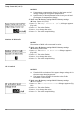
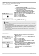

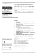
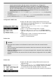
Table Of Contents
- 1 General information
- 2 Quick guide
- 3 Overview
- 4 Installation of the base system
- 5 Initial commissioning of the base system
- 6 Installation and initial commissioning of optional components
- 6.1 Commissioning the SD card (MPPT 6000-M only)
- 6.2 AUX 1,2,3 relay output connection (MPPT 6000-M only)
- 6.3 AUX IO remote control input connection (MPPT 6000-M only)
- 6.4 PA TS-S external temperature sensor connection
- 6.5 StecaLink slave connection
- 6.6 StecaLink master connection (MPPT 6000-M only)
- 6.7 UART/RS-232 interface connection (MPPT 6000-M only)
- 6.8 Redundancy function (MPPT 6000-S only)
- 6.9 Install cable strain relief
- 7 Display (layout, function, operation)
- 8 System functions
- 8.1 Protection functions
- 8.2 Battery type setting
- 8.3 Current limit system setting (MPPT 6000-M only)
- 8.4 Current limit device setting
- 8.5 Lead-acid battery system functions
- 8.5.1 Equalisation cycle mode
- 8.5.2 Battery control mode (MPPT 6000-M only)
- 8.5.3 Battery capacity test (MPPT 6000-M only)
- 8.5.4 Battery type
- 8.5.5 Battery capacity
- 8.5.6 Current limit system (MPPT 6000-M only)
- 8.5.7 Current limit device
- 8.5.8 Charge voltages
- 8.5.9 IUIA charge mode (MPPT 6000-M only)
- 8.5.10 Start boost charge
- 8.5.11 Battery temperature sensor
- 8.5.12 Cable compensation
- 8.5.13 PV string connection
- 8.5.14 Expert menu
- 8.6 Li-Ion battery system functions (MPPT 6000-M only)
- 8.7 NiCd battery system functions (MPPT 6000-M only)
- 8.8 StecaLink bus
- 8.9 Internal data logger
- 8.10 Clear log data
- 8.11 Clear event log
- 8.12 Factory settings
- 8.13 UART/RS-232 interface (MPPT 6000-M only)
- 8.14 Acoustic alarm
- 8.15 SD card (MPPT 6000-M only)
- 9 Control functions via AUX 1/2/3 (MPPT 6000-M only)
- 10 Troubleshooting
- 11 Maintenance, dismounting and disposal
- 12 Technical data
- 13 Guarantee conditions, exclusion of liability, contacts, notes

Selecting the MPPT slave
✔
‘Main menu è System settings è StecaLink master menu
è Change slave settings’
1. Press SET. The Change slave settings dialogue appears
with a list of the recognised StecaLink slave members. The list
is sorted by increasing order of the member addresses (Fig
left).
2.
Press D, Ñ to select the MPPT 6000-S whose settings are to be
changed.
3. Press SET. The Settings MPPT slave dialogue appears,
with the configuration menu for the MPPT 6000 (Fig. left).
Changing Tarom MPPT 6000-S slave settings
Name
NOTICES
n An individual name can be assigned to each StecaLink
MPPT 6000-S.
n Assignment of a name is optional and is not required for
operating the device.
n The name is shown in the measurements display on the
status screen.
n The following applies to the MPPT 6000-S:
–
The MPPT 6000 device name is assigned as fixed
value.
n The following printable ASCII characters can be used for
entering an individual name: !"#$%&'()*+,-./
0123456789:;<=>?
@ABCDEFGHIJKLMNOPQRSTUVWXYZ[\]^_`abcdefghijklm
nopqrstuvwxyz{|}~
n An individual name with a length of up to 8 characters
can be entered.
✔
‘Main menu è System settings è StecaLink master menu
è Change slave settings è Selection [ xx - MPPT 6000]
è Name’
1. Press SET. The Set slave display name
dialogue appears
(Fig. left).
2.
Press D, Ñ to select the character position.
3. Press SET. The entry position blinks.
4.
Press D, Ñ to select the desired character.
5. Press SET. The entry position stops blinking.
The selected character is adopted.
6.
Repeat steps 2.-5. until the desired name with max. 8
characters has been entered.
7. Press Ñ to exit the data entry dialogue.
756.404 | Z01 | 16.06
88