
User manual

NOTICE!
Risk of damage to the inverter and the modules. Connect the opposing connectors for the
DC connections to the DC cable, observing the correct polarity.
Attach the connector plug counterparts to the DC cable according to the manufacturer's
instructions; see Appendix.
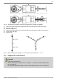
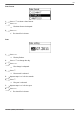
4.5 Preparing the data connection cable
If a data connection is required, use a standard RJ45 cable (patch cable, Cat5) or construct an
alternative data connection cable(see
Ä
Further information on page 30).
4.6 Connecting the inverter inverter and switching the AC on
DANGER!
Risk of death by electrocution! Observe the hazard warnings under
Ä
Chapter 4.1 „Safety
measures during installation“ on page 33.
NOTICE!
– Between the data connection cables (RS485/Ethernet) and the DC/AC lines, maintain a
distance of 200 mm, to avoid interference in the data transmission.
– The protection class IP65 for type coolcept-x is only ensured if the AC and DC plugs are
plugged in and the RJ45 sockets are sealed with sealing caps.
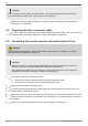
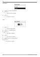
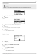
1. If necessary, establish the data connection:
n Connect the inverters and the master with data connection cables.
n On the last inverter, switch on the termination (slide switch).
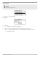
2. Seal open RJ45 sockets with sealing caps.
3. Forcefully press the plug connector mating piece (DC cable) into the DC connection on the
inverter until it audibly locks in place.
4. Plug the AC connector onto the coupling on the inverter, until the plug audibly locks in place.
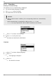
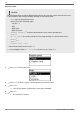
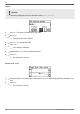
5. Switch on the AC miniature circuit breaker. The start page for 1st commissioning is shown on
the display.
6. Perform 1st commissioning and switch on the DC supply, as described in
EN
747.431 | Z09.3 | 2017-09-05
42