
Instructions


A.4 Phoenix Contact SUNCLIX (DC connector)
PHOENIX CONTACT GmbH & Co. KG
32823 Blomberg, Germany
Phone +49-(0)5235-3-00
PV-CF-S 2,5-6 (+) 1774674
PV-CM-S 2,5-6 (-) 1774687
www.phoenixcontact.com MNR 0140682 - 03 2013-04-18
© PHOENIX CONTACT 2013-04-18 MNR 0140682 - 03 10520503
SUNCLIX-Photovoltaik-Steckverbinder zum
Einsatz in Photovoltaik-Anlagen für
2,5-6 mm²-Solarkabel vom Typ PV1-F oder für
UL-zertifiziertes Solarkabel
(ZKLA), AWG 10–14
1 Sicherheitshinweise
WARNUNG: Die SUNCLIX-Steckverbin-
der dürfen ausschließlich durch elektro-
technisch unterwiesene Personen
angeschlossen werden.
WARNUNG: Stecken oder trennen Sie die
SUNCLIX-Steckverbinder niemals unter
Last.
ACHTUNG: Verwenden Sie diese Steck-
verbinder nur zusammen mit einem
2,5-6 mm²-Solarkabel vom Typ PV1-F
oder UL-zertifiziertem Solarkabel (ZKLA
Kupferlitze, AWG 10 – 1 4). Nur mit diesem
Kabel ist der sichere elektrische An-
schluss gewährleistet. Weitere Kabelty-
pen sind auf Anfrage möglich. Beachten
Sie beim Verlegen des Kabels die Bieger-
adien, die der Hersteller vorgibt.
ACHTUNG: Verbinden Sie diese Steck-
verbinder nur mit anderen SUNCLIX-
Steckverbindern. Beachten Sie bei dem
Verbinden unbedingt die Angaben zu
Nennspannung und Nennstrom. Der
kleinste gemeinsame Wert ist zulässig.
ACHTUNG: Schützen Sie die Steckver-
binder vor Feuchtigkeit und Schmutz.
– Tauchen Sie die Steckverbinder nicht un-
ter Wasser.
– Verlegen Sie den Stecker nicht direkt auf
der Dachhaut.
– Versehen Sie die Steckverbinder, die nicht
gesteckt sind, mit einer Schutzkappe (z. B.
PV-C PROTECTION CAP, 1785430).
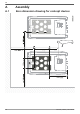
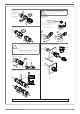
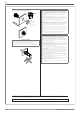
2Steckverbinder anschließen
2.1 Kabel anschließen (Bild )
• Isolieren Sie das Kabel mit einem geeigneten
Werkzeug um 15 mm ab. Achten Sie darauf,
dabei keine Einzeldrähte abzuschneiden.
1
Führen Sie die abisolierte Ader mit verdrillten
Litzen sorgfältig bis zum Anschlag ein. Die
Litzenenden müssen in der Feder sichtbar sein.
2 Schließen Sie die Feder. Stellen Sie sicher,
dass die Feder eingerastet ist.
3 Schieben Sie den Einsatz in die Hülse.
4 Ziehen Sie die Kabelverschraubung mit 2 Nm
an.
2.2 Steckverbinder zusammen fügen
• Führen Sie Stecker und Buchse zusammen.
Dabei rastet die Verbindung ein.
• Ziehen Sie an der Kupplung, um die korrekte
Verbindung zu prüfen.
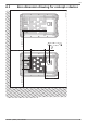
3 Steckverbinder trennen (Bild )
Sie benötigen einen Schlitz-Schraubendreher mit
3-mm-breiter Klinge
(z. B. SZF 1-0,6X3,5, 1204517)
.
1 Führen Sie den Schraubendreher ein, wie in
Bild gezeigt.
2 Lassen Sie den Schraubendreher stecken und
trennen Sie Buchse und Stecker voneinander.
3.1 Kabel lösen (Bild )
1 Drehen Sie die Kabelverschraubung auf.
2 Führen Sie den Schraubendreher ein, wie in
Bild gezeigt.
3 Hebeln Sie die Verbindung auf und ziehen Sie
Hülse und Einsatz auseinander.
4 Öffnen Sie die Feder mit dem Schraubendre-
her. Entfernen Sie das Kabel.
SUNCLIX photovoltaic I/O connector for in-
stallation in photovoltaic systems for
2,5-6 mm² solar cables, type PV1-F or for so-
lar cables with UL certification
(ZKLA),
AWG 10–14
1Safety notes
WARNING: The SUNCLIX plug-in con-
nectors may be connected only by trained
electricians.
WARNING: Never plug in or disconnect
the SUNCLIX plug-in connectors under
load.
NOTE: Use these plug-in connectors only
together with a 2,5-6 mm² PV1-F type so-
lar cable or a UL-certified solar cable
(ZKLA copper litz wires, 10-14 AWG). A
safe electrical connection is only possible
with this cable. Other cable types are avail-
able on request.
When laying out the cable, observe the
bending radiuses that the manufacturer
specifies.
NOTE: Connect this plug-in connector
only with other SUNCLIX plug-in connec-
tor. When making the connections, be sure
to observe the specifications on nominal
voltage and nominal current. The smallest
common value is permissible.
NOTE: Protect the plug-in connectors
from humidity and dirt.
– Do not immerse the plug-in connector in
water.
– Never lay out the plug directly on the roof-
ing.
– Attach a protective cap (e.g.
PV-C PROTECTION CAP, order number
1785430) to plug-in connectors that are
not plugged in.
2 Connecting connectors
2.1 Connecting the cable (Fig. )
• Strip the cable with a suitable tool by 15 mm.
Make sure that no individual wires are cut off.
1 Carefully insert the stripped wire with twisted
litz wires all the way in. The litz wire ends have
to be visible in the spring.
2 Close the spring. Make sure that the spring is
snapped in.
3 Push the insert into the sleeve.
4 Tighten the cable gland to 2 Nm.
2.2 Assemble the connector
• Bring the plug and the socket together. The
connection snaps close thereby.
• Pull on the coupling to check the proper con-
nection.
3 Separating the connector (Fig. )
You need a slot screwdriver with a 3-mm wide
blade (e.g. SZF 1-0.6X3.5; item no. 1204517).
1 Insert the screwdriver as shown in Fig. .
2 Leave screwdriver inserted and disconnect the
plug and the socket from each other.
3.1 Loosen the cable (Fig. )
1 Screw open the cable gland.
2 Insert the screwdriver as shown in Fig.
3 Pry the connection open and pull the sleeve
and the insert apart.
4 Open the spring with the screwdriver. Remove
the cable.
Connecteur photovoltaïque SUNCLIX destiné
aux câbles pour systèmes à énergie solaire
de 2,5-6 mm², type PV1-F ou homologués UL
(ZKLA), AWG 10 – 14
1 Consignes de sécurité
AVERTISSEMENT : Seuls des per-
sonnes dûment formées en électrotech-
nique sont autorisées à installer les
connecteurs mâles SUNCLIX.
AVERTISSEMENT : Les connecteurs
SUNCLIX ne doivent jamais être décon-
nectés en charge.
IMPORTANT : Utiliser ces connecteurs
exclusivement avec un câble pour sys-
tème à énergie solaire de 2,5-6 mm², de
type PV1-F ou un câble homologué UL (fil
de cuivre ZKLA, AWG 10 – 14). Seul ce
câble est en mesure de garantir la sécurité
électrique du raccordement. Autres types
de câble possibles sur demande. Lors de
la pose du câble, respecter les rayons de
courbure prescrits par le fabricant.
IMPORTANT : Raccorder ces connec-
teurs mâles uniquement avec d'autres
connecteurs SUNCLIX. Lors du raccorde-
ment, respecter impérativement les va-
leurs données pour la tension nominale et
pour l'intensité nominale. Le plus petit dé-
nominateur commun est autorisé.
IMPORTANT : Protéger les connecteurs
mâles de l'humidité et de la saleté.
– Ne jamais plonger les connecteurs mâles
dans l'eau.
– Ne jamais poser directement le connec-
teur sur la peau du toit.
– Equiper les connecteurs mâles non enfi-
chés d'un capuchon de protection (par ex.
PV-C PROTECTION CAP, 1785430).
2 Raccordement du connecteur
2.1 Raccordement du câble (Figure )
• Dénuder le câble sur 15 mm avec un outil ap-
proprié. Veiller à ne sectionner aucun fil du
câble.
1 Introduire avec prudence le fil dénudé aux
brins torsadés jusqu'en butée. Les extrémités
des cordons doivent apparaître dans le
« tiroir » à ressort.
2 Refermer le « tiroir » à ressort. Vérifier qu'il est
bien encliqueté.
3 Enfiler le raccord dans le manchon.
4 Serrer le presse-étoupe à 2 Nm.
2.2 Assemblage du connecteur mâle
• Assembler le connecteur et le connecteur fe-
melle. Veiller à ce que la connexion s'encli-
quète.
• Exercer une traction des deux côtés du raccor-
dement pour en vérifier la solidité.
3 Déconnexion du connecteur mâle
Un tournevis à fente à lame large de 3 mm est re-
quis (par ex. SZF 1-0,6X3,5 ; référence 1204517).
1 Introduire un tournevis com. indiqué à la
Fig. .
2 Laisser le tournevis en place et séparer les
connecteurs mâle et femelle l'un de l'autre.
3.1 Séparation du câble (Fig. )
1 Dévisser le raccord vissé du câble.
2 Introduire un tournevis com. indiqué à la
Fig.
.
3 Soulever la liaison puis séparer le manchon du
raccord.
4 Ouvrir le « tiroir » à ressort avec le tournevis.
Extraire le câble du connecteur.
Connettore fotovoltaico SUNCLIX per l'utiliz-
zo in impianti fotovoltaici per cavo solare da
2,5-6 mm² del tipo PV1-F o cavo solare certifi-
cato UL (ZKLA), AWG 10 – 14
1 Avvertenze di sicurezza
AVVERTENZA: I connettori SUNCLIX de-
vono essere collegati solo da persone che
operano sotto la supervisione di elettricisti
specializzati.
AVVERTENZA: Collegare o scollegare i
connettori SUNCLIX soltanto in assenza di
carico.
IMPORTANTE: Utilizzare questi connetto-
ri soltanto insieme a un cavo solare da
2,5-6 mm² del tipo PV1-F o un cavo solare
certificato UL (cavo di rame ZKLA,
AWG 10 – 14). Solo con questo cavo si
garantisce il collegamento elettrico sicuro.
Altri tipi di cavo sono possibili su richiesta.
Per la posa del cavo rispettare i raggi di
curvatura prescritti dal produttore.
IMPORTANTE: Collegare questi connet-
tori soltanto con altri connettori SUNCLIX.
Per il collegamento rispettare assoluta-
mente le indicazioni sulla tensione nomi-
nale e la corrente nominale. È permesso il
più piccolo valore comune.
IMPORTANTE: Proteggere dalla polvere
e dall'umidità i connettori.
– Non immergere in acqua i connettori.
– Non posare il connettore direttamente sul
manto di copertura del tetto.
– Applicare un cappuccio di sicurezza
(ad es. PV-C PROTECTION CAP, codice
1785430) ai connettori non collegati.
2 Collegamento del connettore
2.1 Collegamento del cavo (figura )
• Spelare il cavo di 15 mm con un utensile adat-
to. Eseguendo questa operazione, fare atten-
zione a non tagliare un singolo filo.
1 Inserire con cura il conduttore spelato con i ca-
vetti intrecciati fino a battuta. Le estremità dei
cavetti devono essere visibili nell'elemento di
bloccaggio a molla.
2 Chiudere l'elemento di bloccaggio a molla. Ve-
rificare che scatti.
3 Infilare l'inserto nel capocorda.
4 Serrare la connessione a vite per cavo con una
coppia di 2 Nm.
2.2 Unione dei connettori
• Congiungere assieme connettore maschio e
connettore femmina. Il collegamento viene
così inserito.
• Tirare il giunto per verificare che il collegamen-
to sia corretto.
3 Separazione dei connettori (Fig. )
È necessario un cacciavite per viti a taglio con una
punta larga 3 mm
(ad es. SZF 1-0,6X3,5; 1204517)
.
1 Inserire il cacciavite come indicato in figura .
2 Lasciare inserito il cacciavite e scollegare il
connettore femmina dal connettore maschio.
3.1 Scollegamento del cavo (Fig. )
1 Svitare la connessione a vite per cavo.
2 Inserire il cacciavite come indicato in figura .
3 Fare leva con forza sul collegamento e stacca-
re il connettore femmina dall'inserto.
4 Aprire l'elemento di bloccaggio a molla con il
cacciavite. Rimuovere il cavo.
4
3
1
2
15
1
2
4
3
1
2
EnglishFrançaisItaliano Deutsch
DE Einbauanweisung
EN Installation notes
FR Instructions d'installation
IT Istruzioni di installazione
ES Instrucciones de montaje
PT Instruções de instalação
RU Инструкция по установке
TR Montaj talimatı
ZH 安装说明
JA 組立説明
Italiano Français English Deutsch
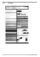
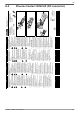
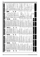
Dati tecnici a norma Caractéristiques techniques selon la norme Technical data according to the standard Technische Daten nach Norm EN 50521 UL SUBJECT 6703
Temperatura ambiente Température ambiante Ambient temperature Umgebungstemperatur -40 °C...+85 °C -40 °C ...+70 °C
Tensione nominale, max. Tension nominale, max. Nominal voltage, max. Nennspannung, max. 1100 V DC 600 V DC
Corrente nominale, max. Intensité nominale, max. Nominal current max. Nennstrom, max. 2,5 mm² - 27 A; 4 mm² - 40 A; 6 mm² - 40 A AWG 14 - 15 A, AWG 12 - 20 A, AWG 10 - 30 A
Diametro cavo Diamètre de câble Cable diameter Kabeldurchmesser 5 ... 8 mm 5 ... 8 mm
Conforms to
UL Outline of Investigation
SUBJECT 6703
Connectors for use in
Photovoltaic Systems
J
RECOGNIZED
COMPONENT
4007180
EN
747.431 | Z09.3 | 2017-09-05
101