In This Section… and Steel City ® Fittings Overview .........................................................................F-2–F-3 Thinwall Conduit Fittings (EMT)........................................F-4–F-9 Rigid/Intermediate Grade Conduit Fittings .......................F-10–17 Flexible Cord and Power Cable Connectors ...........................F-18 Liquidtight Flexible Metal Conduit and Connectors.......F-19–F-23 Non-Metallic Sheathed Cable Fittings ..........................F-24–F-25 Service Caps...
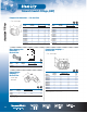
Overview Steel City Fittings Fittings ® Steel City® Conduit Fittings provide long-lasting service in commercial, industrial and residential construction. Our fittings are manufactured within strict tolerances to maintain consistent performance. Installers can be assured that every fitting with the Steel City® name will work every time. So when you select Steel City® Conduit Fittings, that means fewer headaches and call-backs.
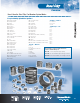
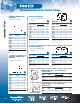
Overview Here’s How the Steel City® Part Number System Works Easy-to-identify alphabetical prefixes: SH – Service Entrance Fitting 2nd Digit — Method BI – Bushings, Insulated SL – Service Ells BL – Blanks SR – Sealing Rings BR – Rigid Spacer SS – Stainless Steel 1 = Compression 2 = Set Screw 3 = Other BS – Box Spacer LS – Locknut, Sealing 3rd/4th Digit — Size BT – Thinwall Spacer TC – Thinwall Connectors BU – Bushings TK – Thinwall Couplings CB – Clamp Back TL – Thinwall Elbow CP – Cable P
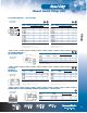
Thinwall Conduit Fittings (EMT) Fittings Set Screw Connectors — Steel • Concrete tight when taped • Zinc plated Non-Insulated Insulated “A” CAT NO. CONDUIT SIZE (IN.) INNER PACK OUTER PACK “A” CAT NO. CONDUIT SIZE (IN.
Thinwall Conduit Fittings (EMT) Compression Couplings — Steel “A” CAT NO. INNER PACK OUTER PACK “A” CAT NO. CONDUIT SIZE (IN.
Thinwall Conduit Fittings (EMT) Compression Connectors — Die Cast Zinc Fittings • 1⁄2"–4" concrete tight A CONDUIT SIZE (IN.) CAT NO. DIMENSIONS (IN.) A B STD. CTN. Non-Insulated B DIMENSIONS (IN.) A B STD. CTN.
Thinwall Conduit Fittings (EMT) Set Screw Connectors — Die Cast Zinc • Concrete tight when taped CAT NO. CONDUIT A (IN.) B SIZE (IN.) TC-221 SERIES TC-821 SERIES (IN.) STD. CTN. CONDUIT A (IN.) B SIZE (IN.) TC-221 SERIES TC-821 SERIES (IN.) CAT. NO. STD. CTN.
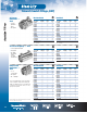
Thinwall Conduit Fittings (EMT) Combination Set Screw Couplings • Concrete tight when taped CONDUIT SIZE (IN.) CAT. NO. A DIMENSIONS (IN.) A B STD. CTN. Fittings Die Cast Zinc Flexible Metal Conduit to EMT TX-220 TX-221 TX-222 TX-223 B ⁄8 Flex to 1⁄2 EMT ⁄2 Flex to 1⁄2 EMT 3 ⁄4 Flex to 3⁄4 EMT 1 Flex to NMT 1 5⁄8 1 13⁄16 1 31⁄32 2 7⁄64 3 1 1 ⁄2 1 5⁄32 1 11⁄32 1 5⁄8 500 250 150 150 UL File No. E-23018. Combination Couplings A Max B CAT. NO. A Min TRADE FIG. SIZE (IN.) A (MIN.
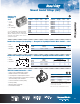
Thinwall Conduit Fittings (EMT) EMT Connectors — Die Cast Zinc Two-Piece Type 90° Angle A B B C C B A A EMT Connector CAT. NO. A B STD. CTN. ⁄2 0.68 1.05 1,000 1 DIMENSIONS (IN.) UL File No. E16592. One-Hole Snap Straps — Steel • Zinc plated TC921 TC-911-SC TC-912-SC DIMENSIONS (IN.) A B C SIZE (IN.) Set Screw Type Compression Type Compression Type ⁄2 ⁄2 3 ⁄4 1.27 1.37 1.86 1 1 1.15 1.15 .95 .45 .45 .52 STD. CTN.
Rigid/Intermediate Grade Conduit Fittings B Set Screw Connectors • Malleable iron/zinc plated • Zinc plated Fittings Threadless Compression Connectors Insulated CAT. NO. SIZE (IN.) DIMENSIONS (IN.) A B STD. CTN. CAT. NO. SIZE (IN.) DIMENSIONS (IN.) A B STD. CTN.
Rigid/Intermediate Grade Conduit Fittings A 90° Short Radius Elbows — Die Cast Zinc B SIZE (IN.) CAT. NO. HL-202-SC The T&B Hub — Zinc Die Cast with Insulated Throat * DIMENSIONS (IN.) A B ⁄4 1.17 3 SHF. CTF./ SHIP QTY. 1.04 25/250 H050-SC Series Hub • The T&B Hub with sealing ring that will not fall out UL Listing E37148.
Rigid/Intermediate Grade Conduit Fittings Fittings Conduit Nipples Iron/Zinc Plated Conduit Nipples Iron/Zinc Plated — Insulated A A B CAT. NO. CONDUIT SIZE (IN.) A 841-TB HA-401 HA-402 HA-403 HA-404 HA-405 HA-406 HA-407 HA-408 HA-409 HA-410 ⁄8 ⁄2 3 ⁄4 1 1 1⁄4 11⁄2 2 2 1⁄2 3 3 1⁄2 4 ⁄16 ⁄64 43 ⁄64 7 ⁄8 1 1⁄8 1 1⁄8 1 7⁄16 1 1⁄4 1 1⁄2 1 3⁄4 — 3 DIMENSIONS (IN.) B STD. CTN.
Rigid/Intermediate Grade Conduit Fittings B B Locknuts Steel / Zinc Plated Locknuts Die Cast Zinc A CAT. NO. CONDUIT SIZE (IN.) DIMENSIONS (IN.) A (MIN.) B (MAX.) ⁄8 ⁄2 3 ⁄4 1 11⁄4 11⁄2 2 2 1⁄2 3 3 1⁄2 4 5 6 — 0.125 0.140 0.170 0.170 0.170 0.187 0.375 0.375 0.438 0.438 0.500 0.561 3 1 STD. CTN. — 1.140 1.420 1.770 2.281 2.598 3.175 3.562 4.250 4.803 5.402 6.674 7.934 1,000 1,000 1,000 500 200 100 50 30 25 25 25 10 10 CAT. NO. CONDUIT SIZE (IN.
Rigid/Intermediate Grade Conduit Fittings Fittings Conduit Bushings Die Cast Zinc — Insulated Metallic B • 105°C thermoplastic liners A • Heavy reinforced ribs CAT. NO. CONDUIT SIZE (IN.) BU-801 BU-802 BU-803 BU-804 BU-805 ⁄2 ⁄4 1 11⁄4 11⁄2 1 3 DIMENSIONS (IN.) A B STD. CTN. CAT. NO. CONDUIT SIZE (IN.) 1.06 1.31 1.59 1.96 2.18 1,000 1,000 500 250 250 BU-806 BU-807 BU-808 BU-809 BU-810 2 21⁄2 3 31⁄2 4 0.43 0.43 0.48 0.56 0.60 UL File No. E-23018.
Rigid/Intermediate Grade Conduit Fittings Insulated Bushings — Iron/Zinc Plated CAT. NO. B CONDUIT SIZE (IN.) BI 901 BI-902 BI-903 BI-904 BI-905 ⁄2 ⁄4 1 1 1⁄4 1 1⁄2 1 3 DIMENSIONS (IN.) A B STD. CTN. CAT. NO. 1 1⁄32 1 1⁄4 1 9⁄16 1 15⁄16 2 13⁄64 1,000 1,000 500 200 100 BI-906 BI-907 BI-908 BI-909 BI910 ⁄2 ⁄2 9 ⁄16 19 ⁄32 5 ⁄8 1 1 UL File No. E-23018. A DIMENSIONS (IN.) A B 2 2 1⁄2 3 3 1⁄2 4 2 45⁄64 3 7⁄32 3 27⁄32 4 7⁄16 4 31⁄32 STD. CTN.
Rigid/Intermediate Grade Conduit Fittings B Reducers — Malleable Iron/ Zinc Plated One-Hole Straps — Steel/Zinc Plated A A Fittings B CONDUIT SIZE (IN.) CAT. NO. RB 421 RB-432 RB-443 ⁄4– 1⁄2 1 ⁄2– 3⁄4 1– 3⁄4 3 DIMENSIONS (IN.) A B STD. CTN. ⁄8 1 11 ⁄16 100 100 50 13⁄16 13⁄16 13⁄16 5 UL File No. E-23018. Reducing Washers — Steel/Zinc Plated A B CAT. NO. CONDUIT SIZE (IN.) A DIAMETER (IN.) B C STD. CTN.
Rigid/Intermediate Grade Conduit Fittings Pipe Straps — Malleable Iron/ Zinc Plated Pipe Spacers for Rigid/Intermediate or Thinwall — Die Cast Zinc A B A B CAT. NO. CONDUIT SIZE (IN.) 10 1 ⁄4 1 ⁄4 1 ⁄4 5 ⁄16 3 ⁄8 1 ⁄2 5 ⁄8 5 ⁄8 5 ⁄8 5 ⁄8 5 ⁄8 ⁄8 ⁄2 3 ⁄4 1 1 1⁄4 1 1⁄2 2 2 1⁄2 3 3 1⁄2 4 5 3 1 DIMENSIONS (IN.) A B STD. CTN.
Fittings Flexible Cord & Power Cable Connectors BLACK BEAUTY® Non-Metallic Liquidtight Strain Relief Connectors Straight TRADE OR HUB CAT. NO. SIZE (IN.
Liquidtight Flexible Metal Conduit and Connectors Liquidtight Flex for Type B Non-Metallic Conduit Standard Material/Finish: • Body/Gland — Nylon-Gray Listed/Certified by: • UL Listed (File # E23018) • O-Ring — Nitrate (Black) • CSA Certified (File # LR52391) • Locknut — Nylon • Conforms to watertight requirements for Type 4 Fittings • Temp. Rating — 80°C • Material Flammability Rating: UL94-V2 Straight B A CAT. NO. C D E Thread LT-500 LT-501 LT-502 LT-503 A5 .015 TRADE (0.40) IN. SIZE (IN.
Liquidtight Flexible Metal Conduit and Connectors Outdoor XTRA FLEX® Raceway System (Type B) Fittings O.D. . . . . . . . . Specifications . . . . . . . . . . • Color: Gray • Length: 100 ft. for LTC038GY thru LTC125GY 50 ft. for LTC150GY and LTC200GY • UL Temperature Rating: 80° C dry, 60° C wet 70° C oil. res.
Liquidtight Flexible Metal Conduit and Connectors Liquidtight Fittings CAT. NO. GROUNDING DEVICE TRADE (LUG ONLY) SIZE CAT. NO. (IN.) 5331GR 5332GR 5333GR 5334GR 5231GR 5232GR 38GR-TB 12GR-TB 34GR-TB 1GR-TB 38GR-TB 12GR-TB B Lug Range A ⁄8 ⁄2 3 ⁄4 1 3 ⁄8 1 ⁄2 3 1 STD. CTN. CAT. NO.
Liquidtight Flexible Metal Conduit and Connectors Straight Connectors • 3⁄8"–1", steel C A • 11⁄4"–4", malleable iron/zinc plated • 3⁄8"–1", steel A Fittings B CAT. NO. • 11⁄4"–4", malleable iron/zinc plated (with insulated throat) CONDUIT SIZE (IN.) A DIMENSIONS (IN.) B C STD. CTN.
Liquidtight Flexible Metal Conduit and Connectors Straight Connectors — Die Cast Zinc (with Insulated Throat) A Straight Connectors — Die Cast Zinc B A B C CAT. NO. C A DIMENSIONS (IN.) B C STD. CTN. CAT. NO. ⁄8 ⁄2 3 ⁄4 1 11⁄4 11⁄2 2 21⁄2 3 3 1⁄2 4 1.81 1.88 2.03 2.28 2.59 2.78 3.22 3.53 3.91 4.04 4.16 0.50 0.61 0.56 0.63 0.69 0.78 0.78 0.84 0.88 0.91 0.94 1.06 1.19 1.44 1.75 2.44 2.75 3.53 4.28 4.72 5.42 5.
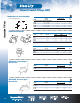
Non-Metallic Sheathed Cable Fittings Fittings All Plastic Connector for NM Cable and Flexible Cord Press locking wedge into cavity that locks onto cable. Snap captive locking wedge into connector’s cavity. Cat. No. 3201 is ideal for multiple flexible cords and cable. • High-impact thermoplastic: UL 94-V1 Size Range • Features push-in design CAT. NO.
Non-Metallic Sheathed Cable Fittings NM Clamp Type Connector — Die Cast Zinc Duplex Clamp Type Connector — Die Cast Zinc B • For use with aluminum, smooth, extruded metal–clad cable. (min. dia. .410 — max. dia. .500). A Max. A Min. CAT. NO. CONDUIT SIZE (IN.) A (MIN.) DIMENSIONS (IN.) A (MAX.) B STD. CTN. NC-201 NC-202 NC-203 NC-204 NC-205 NC-206 ⁄2 ⁄4 1 11⁄4 13⁄8 2 0.40 0.50 0.62 0.50 0.75 0.90 0.95 1.10 1.14 1.38 1.61 2.04 1.87 1.84 2.00 2.28 2.49 3.
Armored Cable/Flexible Metallic Conduit Fittings Fittings Straight Squeeze-Type Connectors — Malleable Iron or Stamped Steel/Zinc Plated CAT. NO. XC-400 XC-401 XC-402 XC-403 XC-404 XC-405 XC-406 XC-407 XC-408 Straight Squeeze-Type Connectors — Insulated Malleable Iron or Stamped Steel/Zinc Plated CONDUIT SIZE (IN.) UNIT QTY. STD. CTN. ⁄8 ( 1⁄2 KO) 1 ⁄2 3 ⁄4 1 1 1⁄4 1 1⁄2 2 2 1⁄2 3 50 25 25 25 5 10 10 5 5 100 100 100 100 10 10 10 5 5 3 CAT. NO. CONDUIT SIZE (IN.) UNIT QTY. STD. CTN.
Armored Cable/Flexible Metallic Conduit Fittings Straight Squeeze-Type Connectors — Insulated — Die Cast Zinc N2 B N2 N1 N1 N3 N3 D F Thread B A Min. A Max. A Min. A Max. A Min. A Max. E C Fig. 1 B Fig. 3 CAT. NO. FIG. SIZE (IN.) A (MIN.) DIMENSIONS (IN.) A (MAX.) B STD. CTN. XC-870 XC-872 XC-873 XC-874 XC-875 XC-876 XC-877 XC-878 XC-879 XC-8710 1 1 2 2 2 3 3 3 3 3 ⁄2 ⁄4 1 11⁄4 11⁄2 2 21⁄2 3 31⁄2 4 0.74 0.88 1.10 1.48 1.68 2.12 2.71 3.15 3.20 3.15 0.92 1.10 1.35 1.65 2.00 2.47 3.
Armored Cable/Flexible Metallic Conduit Fittings Steel City® Cable Lok® Fittings • Simple, one-piece installation with no locknuts • Screw designed for exceptional pullout resistance • Captive screw ensures that the screw is intact for installation and resists backing out after installation • Corrosion-resistant, zinc-chromatic plating Simple, fast steps to install the Steel City® Cable Lok®.
Armored Cable/Flexible Metallic Conduit Fittings 90° Clamp Type Connectors — Die Cast Zinc G F G A B C H A B E B E D A Min. D B Max. Threads H Threads C A A E F B Fittings Fig. 2 Fig. 1 Threads F Fig. 3 E F B D D C C Threads G Threads G Fig. 5 Fig. 4 XC-290 Insulated Die Cast Zinc CAT. NO. FIG. XC-290 XC-291 XC-292 XC-293 XC-294 XC-295 XC-296 XC-297 XC298 XC-299 XC-2910 1 1 1 2 2 3 3 4 5 4 4 SIZE (IN.
Armored Cable/Flexible Metallic Conduit Fittings Snap-In Connector for Flexible Metal Conduit — 105° C Rated 4 Metal Grounding Tabs A Fittings • No locknut required Plastic Body • No special tools required • High-impact thermoplastic with steel insert B C CAT. NO. CONDUIT SIZE (IN.) 100-TB 100BP KO SIZE (IN.) UNIT QTY. STD. CTN. ⁄2 ⁄2 50 250 500 1,000 SIZE UNIT QTY. STD. CTN.
Armored Cable/Flexible Metallic Conduit Fittings, Service Caps A Screw-In Connectors Die Cast Zinc — Non-Insulated Water-Tight Connectors B A • For type SE, style U, flat; 2 insulating conductors, 1 bare B SIZE (IN.) XC-240 XC-241 XC-242 XC-243 XC-244 XC-245 XC-246 3 ⁄8 ( 1⁄2 KO) 1 ⁄2 3 ⁄8 1 11⁄4 11⁄2 2 DIMENSIONS (IN.) A B 1.31 1.38 1.62 1.94 2.12 2.31 2.58 STD. CTN. 0.92 0.92 1.12 1.37 1.75 2.13 2.67 500 500 125 125 50 50 50 UL File No. E-23018. CSA File No. LR-18130M57 3⁄8"– 1⁄2".
Cable Caps, Protector, Straps and Clips; Threaded Rod and Coupling Service Cable Caps — Oval One-Hole Strap for 3⁄8" Armored Cable and Flexible Metal Conduit Fittings B A C CAT. NO. STD. CTN. WT./100 (LBS.) FS100-SC 250 1.70 B C Service Cable Straps — One-Hole A CAT. NO. FITS CABLE A DIMENSIONS (IN.) B C STD. CTN. 50130 50130A To 2/0–3 To 4/0–3 5.00 6.75 3.31 4.62 4.75 6.00 10 5 3#3–2 3#3/0–4/0 2.37 4.93 2.12 3.12 2.25 3.
Beam Clamps Beam Clamps D Conduit/Pipe to Beam Clamps 5/16-18 x 13⁄ 8" hex head, cup point, hardened steel, cap screw note 1 ⁄ 8" Min 3 • For mounting pipe or conduit at right angles to the beam • Add a SS316 suffix for stainless steel SIZE CAT. NO. (IN.) TAPPED C B Cup Point BC1-TB 1 BC2-TB 215⁄ 16 1 3 ⁄ 4–20 ⁄ 8–16 DIMENSIONS (IN.) A B C D 1 ⁄ 16 1 ⁄ 8 21⁄ 8 21⁄ 16 11 3 5 3 STD. CTN. CAT. NO.
Ground Clamps, Pipe Hangers Fittings Ground Clamps — Die Cast Zinc, Brass Colored • Two-screw ground connection for armored ground wire CAT. NO. GC-203-B CONDUIT SIZE (IN.) STD. CTN. ⁄2; 1 200 1 6H Series Conduit and Pipe Hangers — Without Bolt RIGID CONDUIT OR PIPE EMT CAT. NO. SIZE (IN.) SIZE (IN.) Without Bolt All Steel City 6H Hanger Bolts include a combination Slot-Phillips Head. For hanging conduit (rigid or EMT) and pipe. The 6H series hangers are fast, easy and economical to use.
Rigid Non-Metallic Conduit A job that normally takes 20 minutes — DONE in 2 minutes or less! Carlon® PVC Conduit Repair System The new, revolutionary Carlon® PVC Conduit Repair System significantly reduces the time and money associated with repairing broken PVC conduits, a.k.a. “stub-ups”, in concrete slabs. Features: • cUL–US Listed • PVC repair fittings are listed in accordance with the NEC® and Section 352.
Rigid Non-Metallic Conduit PVC Conduit Repair Fittings Non-Metallic Rigid Conduit, Fittings and Accessories E2969 Broken conduit on jobsite Coupling E910_ Male Threaded Adapter E920_ Instructions: 1 2 Cut broken conduit off flush. Insert plug to keep conduit clean/dry through balance of rough-in. Once rough-in is complete, remove plug and continue with Step 3. 4 The guide will direct the cutter; the stop will touch when completed.
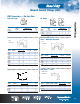
Rigid Non-Metallic Conduit Schedule 40 Elbows ETL Listed to UL 651 in compliance to the NEC® Standard Radius ITEM 90° ELBOW 30° ELBOW 221⁄2° ELBOW BELLED END CAT. NO.
Rigid Non-Metallic Conduit Schedule 40 Elbows Non-Metallic Rigid Conduit, Fittings and Accessories Special Radius F-38 *Consult factory for additional sizes/configurations PLAIN SEGMENT 90° ELBOW PLAIN END CAT. NO. ETL Listed to UL 651 in compliance to the NEC® BELLED NOM. END END DIAM. RADIUS STD. CAT. NO. (IN.) (IN.) CTN.
Rigid Non-Metallic Conduit Schedule 40 Elbows Special Radius *Consult factory for additional sizes/configurations PLAIN SEGMENT 30° ELBOW PLAIN END CAT. NO. BELLED NOM. END END DIAM. RADIUS STD. CAT. NO. (IN.) (IN.) CTN.
Rigid Non-Metallic Conduit Schedule 80 Elbows Non-Metallic Rigid Conduit, Fittings and Accessories Standard Radius ITEM 90° ELBOW 45° ELBOW 30° ELBOW 221⁄2° ELBOW 111⁄4° ELBOW For use with non-metallic solvent weld fittings. PLAIN END CAT. NO. BELLED END CAT. NO.
Rigid Non-Metallic Conduit Schedule 80 Elbows Continued from previous page ETL Listed to UL 651 in compliance to the NEC® Special Radius PLAIN SEGMENT 45° ELBOW 221⁄2° ELBOW 111⁄4° ELBOW BELLED NOM. END END DIAM. RADIUS STD. CAT. NO. (IN.) (IN.) CTN.
Canadian Rigid Non-Metallic Conduit Canadian Schedule 40 Elbows Non-Metallic Rigid Conduit, Fittings and Accessories Standard Radius BELLED END CAT. NO. ITEM 90° ELBOW UA9ADCB-CTN UA9AECB-CTN UA9AFCB-CTN UA9AGCB-UPC UA9AHCB-UPC UA9AJCB-UPC UA9AKCB-CTN UA9ALCB-UPC UA9AMCB UA9ANCB UA9APCB UA9ARCB UA7AGCB UA7AHCB UA7AJCB UA7AKCB UA7ALCB UA7AMCB UA7ANCB UA7APCB UA7ARCB UA6AJCB UA6ANCB UA6ARCB 45° ELBOW 30° ELBOW Standard Radius Elbow Dimensions BELLED END SIZE (IN.) STD. CTN.
Rigid Non-Metallic Conduit Fittings (for use with Schedule 40 & 80 Conduit) Couplings Expansion Fittings E945 series expansion fittings are designed to compensate for length changes due to temperature variations in exposed conduit runs. E23018 Standard Couplings LR33856 E23018 Except where noted by All socket fittings should be attached using Carlon® solvent cement.
Rigid Non-Metallic Conduit Fittings Non-Metallic Rigid Conduit, Fittings and Accessories (for use with Schedule 40 & 80 Conduit) Couplings Adapters Special Long Line Couplings — Sleeve Couplings Female Adapters E23018 Except where noted by Sleeve Coupling (For Repair Work) No Internal Stop CAT. NO. SIZE (IN.) STD. CTN. STD. WT. (LBS.) LENGTH (IN.
Rigid Non-Metallic Conduit Fittings (for use with Schedule 40 & 80 Conduit) Plugs Adapters LR31146 Box Adapters for Enclosures Adapts non-metallic conduit to all electrical enclosures by inserting adapter through knockout and cementing into Carlon couplings. Reducer Plugs CAT. NO. E971C E971D E996D E996E E996F E996G E996H E996J E996K E996L E996N SIZE (IN.) STD. CTN. MIN OD (IN.) MAX CM (IN.) L (IN.) D (IN.) TYPICAL X (IN.
Rigid Non-Metallic Conduit Fittings (for use with Schedule 40 & 80 Conduit) Caps Offsets Non-Metallic Rigid Conduit, Fittings and Accessories Service Entrance Caps E13938 SIZE CAT. NO. (IN.) E995G E995J 11⁄4 2 LR31146 STD. CTN. OFFSET (IN.) A (IN.) 15 8 0.758 0.684 4.230 4.270 Offset CAT. NO. E998D E998E E998E-CAR E998F E998F-CAR E998G-CAR E998H-CAR E998J-CAR E998K-UPC E998L E998N SIZE (IN.) STD. CTN. E ⁄2 3 ⁄4 3 ⁄4 1 1 11⁄4 11⁄2 2 21⁄2 3 4 5 20 5 15 5 5 5 5 2 2 2 1.76 1.76 1.76 2.
Rigid Non-Metallic Conduit Accessories, Conduit Bodies Washers Sleeves Flat Sealing Washer HOLFORM™ Concrete Sleeves Where a waterproof termination is required into any enclosure (metallic or non-metallic), install the neoprene washer over the threads of a terminal adapter before inserting into the enclosure. Use a standard locknut or threaded bushing to secure the assembly. HOLFORM™ non-metallic concrete sleeve forms are the easy way to form holes in concrete.
Conduit Bodies Feature unthreaded hubs and textured lids with foam-in-place gaskets. Conduit Bodies LR31146 Non-Metallic Rigid Conduit, Fittings and Accessories Type LB Type LR SIZE CAT. NO. (IN.) E986D E986E E986F E986G E986H E986J E986K E986L E986M E986N STD. TYPICAL MAX. CTN. C L1 ⁄2 3 ⁄4 1 11⁄4 11⁄2 2 21⁄2 3 31⁄2 4 25 15 10 10 10 10 4 4 4 4 1 ⁄16 29 ⁄32 29 ⁄32 13⁄32 13⁄32 15⁄32 15⁄8 15⁄8 125⁄32 125⁄32 45⁄16 69⁄32 69⁄32 731⁄32 731⁄32 931⁄32 147⁄8 147⁄8 1723⁄32 1723⁄32 11 DIMENSIONS (IN.
Junction Boxes Molded Non-Metallic Junction Boxes — 6P Rated Type 6P enclosures are intended for indoor or outdoor use, primarily to provide a degree of protection against contact with enclosed equipment, falling dirt, hose-directed water, entry of water during prolonged submersion at a limited depth and external ice formation.
Non-Metallic Rigid Conduit, Fittings and Accessories Junction Boxes Large PVC Junction Boxes/ NEMA 4X Large PVC Junction Boxes are fabricated from Type II PVC sheet. Reduce the use of steel boxes and keep your wiring connections clean, safe and dry using these high-quality, fully gasketed junction boxes.
Switch Boxes Single-Gang FS Boxes LR31146 Where noted by Type FSS • For dead-end terminations • For multiple dead-end circuit terminations or where additional support is required in stub-up applications • All sizes take standard covers and accessories or devices • All sizes take standard covers and accessories or devices • Integral mounting feet provide easy mounting • Detachable mounting feet provide easy mounting CAT. NO.
Switch Boxes Non-Metallic Rigid Conduit, Fittings and Accessories Single-Gang FD Deep Device Boxes Type FDC • For terminations where hub requirements vary according to application — hubs easily made with flared wood bit or hole saw • For through terminations where large devices or additional wiring capacity is required • All sizes take standard covers and accessories or devices • All sizes take standard covers and accessories or devices • Integral mounting feet provide easy mounting • Integral mount
Switch Boxes Two-Gang FS Boxes Type 2FSC LR31146 Where noted by Type 2FSE E11461 • All sizes take standard covers and accessories or devices • All sizes take standard covers and accessories or devices • Integral mounting feet provide easy mounting • Integral mounting feet provide easy mounting CAT. NO. CAT. NO. E9812D CE9812D-CTN E9812E CE9812E-CTN E9812F C9812F SIZE (IN.) VOL. CU. IN. STD. CTN. ⁄2 ⁄2 3 ⁄4 3 ⁄4 1 1 32 32 32 32 32 32 10 10 10 10 10 10 1 1 Canada Only SIZE (IN.) VOL. CU. IN.
Support Straps Non-Metallic Rigid Conduit, Fittings and Accessories Snap Strap™ Conduit Support Straps Carlon’s Snap Strap™ offers a unique support strap designed especially for the installation of PVC conduit. Also usable for installations of rigid steel. This high-strength, non-metallic clamp enables conduit to expand and contract freely, eliminating the bowing commonly seen from the expansion and contraction of conduit caused by varying temperature changes.
Clamps Non-Metallic Clamps Non-metallic clamps offer the same chemical resistance as Carlon® non-metallic conduits for a complete, corrosion-resistant system. To be used in accordance with conduit spacing requirements per the NEC®, Section 352.30 and 12-1114 of the CEC. • UV inhibited for use in direct sunlight Conduit Clamps CAT. NO. E977DC E977EC E977FC E977GC E977HC E977JC E977KC-CAR E977LC-CAR E977NC-CAR SIZE IN.
Non-Metallic Rigid Conduit, Fittings and Accessories Clamps Carlon® Masonry Pipe Clamps Carlon® Masonry Pipe Clamps make installations faster and easier by eliminating the use of bolts and anchors. The one-piece design features an anchoring projection designed to push into a 5⁄16" drill hole. The clamps are used to securely support pipe/conduit and electrical cables on concrete and masonry block, and unlike metallic clamps Carlon® Masonry Clamps won’t rust or corrode.
Technical Specifications Corrosion Resistance of Carlon® Schedule 40 and Schedule 80 Fittings Carlon Schedule 40 and Schedule 80 Fittings are generally acceptable for use in environments containing the chemicals below. These environmentalresistance ratings are based upon tests where the specimens were placed in complete submergence in the reagent listed.
Rigid Non-Metallic Utility Conduit Non-Metallic Rigid Conduit, Fittings and Accessories Deep-Socket Schedule 40 Utility Elbows with Integral Belled Ends F-58 SEGMENT CAT. NO. NOM. DIA. (IN.) 90° SWEEP UC9BHB UC9DHB UC9FHB UC9BJB UC9DJB UC9FJB UC9HJB UC9DKB UC9FKB UC9DLB UC9FLB UC9DNB UC9FNB UC9HNB UC9FRB UC9HRB 11⁄2 11⁄2 11⁄2 2 2 2 2 21⁄2 21⁄2 3 3 4 4 4 6 6 RADIUS (IN.) STD. CTN. STD. WT. (LBS.) 12 24 36 12 24 36 48 24 36 24 36 24 36 48 36 48 20 1 1 1 1 1 1 1 1 1 1 1 1 1 1 1 25.00 2.13 3.
Rigid Non-Metallic Long Belled Utility Conduit Non-UL Listed CAT. NO. 90° ELBOW UC9CJBLB UC9DJBLB UC9DLBLB UC9DNBLB UC9DPBLB UC9FJBLB UC9FLBLB UC9FNBLB UC9FPBLB UC9FRBLB UC9HJBLB UC9HLBLB UC9HNBLB UC9HPBLB UC9HRBLB RADIUS (IN.) STD. CTN. STD. WT. (LBS.) 2 2 3 4 5 2 3 4 5 6 2 3 4 5 6 18 24 24 24 24 36 36 36 36 36 48 48 48 48 48 1 1 1 1 1 1 1 1 1 1 1 1 1 1 1 1.3 1.4 5.0 5.8 8.5 2.2 5.2 7.8 11.1 9.6 2.8 12.0 9.7 13.7 18.1 SEGMENT CAT. NO.
P&C Duct Special California Type DB-100 Sweeps — Belled Non-Metallic Rigid Conduit, Fittings and Accessories CAT. NO. F-60 90° SWEEP — 48" RADIUS PE9HN PE9HP CAT. NO. 45° SWEEP — 150" RADIUS PE7SP SIZE (IN.) STD. CTN. 4 5 1 1 SIZE (IN.) STD. CTN. 5 1 *Consult your Thomas & Betts Sales Team for additional sizes CAT. NO. 111⁄4° SWEEP — 150" RADIUS PE3SP SEGMENTED SWEEPS PE3SNS PE3SPS PE3SRS SIZE (IN.) STD. CTN.
P&C Duct DB-60 Sweeps CAT. NO. 90° SWEEP PF9CH PF9CJ PF9CL PF9CN PF9DF PF9DH PF9DJ PF9DL PF9DN PF9DP PF9FF PF9FJ PF9FL PF9FN PF9FP PF9FR PF9HL PF9HN PF9HP PF9HR PF9IL PF9IN PF9IP PF9IR PF9SH PF9SJ PF9SL PF9SR PF9VL PF9VN PF9VP SIZE (IN.) RADIUS (IN.) STD. CTN.
P&C Duct Non-Metallic Rigid Conduit, Fittings and Accessories DB-60 Sweeps SEGMENT CAT. NO. 30° SWEEP PF6CJ PF6CL PF6DL PF6DN PF6DP PF6CH PF6FJ PF6FL PF6FN PF6FR PF6HJ PF6HN PF6HP PF6HR PF6IN PF6IP PF6SJ PF6SN PF6SP PF6VJ PF6VN PF6VR PH5DL PF5DN PF5DP PF5FF PF5FL PF5FN PF5FP PF5FR PF5HL PF5HN PF5HR PF5IJ PF5IL PF5IP PF5IR PF5SL PF5SN PF5SP PF5SR PF5VN PF5VP PF5VR 221⁄2° SWEEP *Consult your Thomas & Betts Sales Team for additional sizes SIZE (IN.) RADIUS (IN.) STD. CTN.
P&C Duct DB-120 Sweeps *Consult your Thomas & Betts Sales Team for additional sizes CAT. NO. SIZE (IN.) RADIUS (IN.) STD. CTN.
P&C Duct Non-Metallic Rigid Conduit, Fittings and Accessories DB-120 Sweeps *Consult your Thomas & Betts Sales Team for additional sizes SEGMENT CAT. NO. SIZE (IN.) RADIUS (IN.) STD. CTN.
P&C Duct (for use with all types of EB and DB Duct) Couplings 5° Angle Coupling BxB (Bell x Bell) Sleeve Coupling (for repair work) CAT. NO. SIZE (IN.) STD. CTN. E200J E200L E200M E200N E200P E200R 2 3 31⁄2 4 5 6 30 25 20 15 8 5 No internal stop CAT. NO. SIZE (IN.) STD. CTN. E2440NF E2440PF E2440RF 4 5 6 15 10 5 5° Angle Coupling B x B (Swedged) Coupling CAT. NO. SIZE (IN.) STD. CTN.
Non-Metallic Rigid Conduit, Fittings and Accessories P&C Duct Adapters End Bells Male Adapter End Bell CAT. NO. SIZE (IN.) STD. CTN. 1 11⁄2 2 3 4 5 6 50 25 50 50 20 5 10 E943F E943H E943J E943L E943N E943P E943R E942F E942H E942J E942L E942N E942P E942R SIZE (IN.) STD. CTN. 1 11⁄2 2 3 4 5 6 50 25 30 25 15 8 6 Reducers Swedge Reducer (Male x Male) CAT. NO. SIZE (IN.) STD. CTN.
P&C Duct Canadian DB/2 Sweeps LR90813 CAT. NO. SIZE (IN.) RADIUS (IN.) STD. CTN.
P&C Duct Canadian DB/2 Duct Fittings End Bells End Bell (For use with DB/2 Duct only) Non-Metallic Rigid Conduit, Fittings and Accessories PVC 5° Coupling B x B — Solvent Weld CAT. NO. SIZE (IN.) STD. CTN. CE245J CE245L CE245N CE245P 2 3 4 5 30 15 10 20 SIZE (IN.) STD. CTN. CE297J CE297L CE297N CE297P 2 3 4 5 40 50 30 15 Adapters PVC Female Adapter — I.P.S. Solvent Weld Duct PE 5° Coupling — Push Fit CAT. NO. SIZE (IN.) STD. CTN. CE2440L CE2440N 3 4 100 90 CAT. NO. SIZE (IN.) STD.
Telephone Duct RUS Accepted Telephone Duct Sweeps Manufactured from Heavy Wall “C” Duct SEGMENT 30° SWEEP • Size: 4" • Each sweep is furnished with a belled end • Straight-end length 3" SEGMENT 45° SWEEP GRAY TP9CN TP9DN TP9FN TP9HN TP9IN TP9JN TP9MN TP9NN TP9SN TP9TN TP9UN WHITE TW9DN TW9FN TW9HN TW9IN TW9JN TW9MN TW9NN TW9SN TW9TN GRAY TP7DN TP7FN TP7HN TP7ON TP7IN TP7JN TP7MN TP7NN TP7RN TP7SN TP7TN TP7UN WHITE TW7DN TW7FN TW7HN TW7ON TW7IN TW7JN TW7MN TW7NN TW7RN TW7SN TW7TN BEND RADIUS STD. CTN.
Non-Metallic Rigid Conduit, Fittings and Accessories Telephone Duct Couplings End Bells Sleeve Coupling Square to Round CAT. NO. SIZE (IN.) STD. CTN. 4x6 4 x 12 4x6 25 10 25 E903N For Repair Work E900N E900NU E900NW (WHITE) Split Sleeve Couplings E900NS E900NS8 (WHITE) E900NSW (WHITE) E900PS No internal stop 4 4x8 4 5 25 15 25 15 SIZE (IN.) STD. CTN. 4 (Sq.) 4 Molded End Bell CAT. NO. E971N SIZE (IN.) STD. CTN.
Telephone Duct Adapters Adapts Telephone Duct to Fiber Transite MCD Adapts Telephone Duct to P&C Duct and Rigid Non-Metallic Conduit Internal Adapter P&C Duct Adapter CAT. NO. STD. CTN. CAT. NO. SIZE (IN.) STD. CTN. 4 24 E913N E913NF 4 4 15 15 4 24 E901N Split E901NS Adapts Threaded Metal Pipe to Telephone Duct Female Adapter CAT. NO. SIZE (IN.) STD. CTN. 4 10 E902N Reducers Adapts Telephone Duct to P&C Duct and Rigid Non-Metallic Conduit P&C Duct Adapter CAT. NO. SIZE (IN.) STD.
Split Duct Split Sleeve Coupling Non-Metallic Rigid Conduit, Fittings and Accessories CAT. NO. SIZE (IN.) DESCRIPTION LENGTH (IN.) SPLIT STD. CTN. STD. WT. (LBS.) 2 21⁄2 3 3 31⁄2 4 4 5 5 6 Split Coupling Split Coupling Split Coupling Split Coupling Split Coupling Split Coupling Split Coupling Split Coupling Split Coupling Split Coupling 6 7 7 6.5 8 8 6 8 9 10 1 1 1 1 1 1 2 1 1 1 25 25 25 25 25 15 25 15 8 6 6.1 21 15.5 10 41.2 16 17 25 16.4 24.
Accessories — PVC Cements No waste • Sprays on in seconds • Fast setting Multi-Purpose Spray-On PVC Cement • Equivalent to a medium-bodied low-VOC, quick-setting clear cement Applications: • For use up to 4" diameter Schedule 40 or 80 PVC electrical conduit • No more spills • Reuse can until empty • Meets ASTM D-2564 • 3-year shelf life • One 4 oz. can is equivalent to 4 oz. of non-aerosol PVC cement* *Equivalence is subject to usage and will vary.
Non-Metallic Rigid Conduit, Fittings and Accessories Accessories — PVC Cements RECOMMENDED PIPE APPLICATION AND SIZES SET-UP TIME (EVAPORATION RATE) RECOMMENDED INSTALLATION TEMP. LAP SHEAR @ 73˚F VISCOSITY AT 75˚ AS MANUFACTURED Recommended for all grades and types of Carlon® wireway and fittings, except Flex-Plus® Blue™ ENT (Electrical Non-Metallic Tubing). Up through 6" diameter. 10˚–30˚F 30˚–50˚F 50˚–70˚F 70˚–90˚F 40˚ to 100˚F 2 hrs. 350 psi 16 hrs. 800 psi 72 hrs.
Accessories — PVC Cements All Weather — Clear RECOMMENDED PIPE APPLICATION AND SIZES SET-UP TIME (EVAPORATION RATE) RECOMMENDED INSTALLATION TEMP. LAP SHEAR @ 73˚F VISCOSITY AT 75˚ AS MANUFACTURED Recommended for all grades and types of Carlon® wireway and fittings, except Flex-Plus® Blue™ ENT (Electrical Non-Metallic Tubing). -5˚–10˚F 10˚–30˚F 30˚–50˚F 50˚–70˚F 70˚–90˚F -5˚ to 100˚F 2 hrs. 350 psi 16 hrs. 800 psi 72 hrs. 1,500 psi 400–700 cps Up through 6" diameter.
Accessories — Sealers Non-Metallic Rigid Conduit, Fittings and Accessories No waste • Sprays on in seconds • Fast setting Sealers Multi-Purpose Weather Gard Spray-On Rubber Film • Weatherproof • Forms a protective weatherproof seal on electrical connections Applications: • Electrical connections • Outdoor lighting • Dries in minutes to crystal clear rubber film • • Prevents corrosion on electrical • connections • • Recommended installation temperatures: 50° to 80°F • • Can be used on wood and plastic P
Accessories — Cement Installation Instructions Cement Joints Cementing PVC Conduit: 1. Make square saw cut with fine tooth saw. 2. Deburr and round inside edge of the cut end. Joining process as follows: 3. Clean socket I.D. and spigot O.D. of dirt and moisture. 4. Apply a uniform coat of cement to spigot end and push onto socket bottom, rotating 1/4 turn. 5. Allow time to set before disturbing. Setting time will depend upon temperature. – Be sure that conduit end is clean and dry.
Non-Metallic Rigid Conduit, Fittings and Accessories Accessories — Conduit Termination, Cutting and Joining Fittings and Adapters for Terminating Non-Metallic Rigid Conduit Terminating Non-Metallic Rigid Conduit is quick and easy utilizing either of the methods indicated below. Terminations may be made in any electrical box or enclosure using standard size knockouts or drilled holes. Method 1.
Accessories — EZ BEND ™ Conduit-Bending Equipment EZ BEND™ ConduitBending Equipment For field bending of small and large diameter non-metallic conduit, the easy answer is EZ BEND™ conduit-bending equipment. • Lightweight • Fast, simple and safe • Less expensive than factory bends • Includes complete instructions and a convenient bending chart EZ BEND™ Conduit-Bending Equipment is designed with the electrical contractor in mind.
Accessories — Rope and Tape Non-Metallic Rigid Conduit, Fittings and Accessories Rope (Conduit Pulling Lines for Conductors or Fiber Optics) F-80 White Diamond Braid Rope This rope is constructed of polyethylene over polyester, designed specifically for fiber optic pulling. The polyethylene jacket gives the “slippery” feel that gives less drag in pulling through conduit. CAT. NO. REEL LENGTHS (FT.) SB14105 5,000 DIAMETER (IN.) ⁄4 1 RECOMMENDED APPROXIMATE WORKING LOAD AVG. TENSILE STD. WT. (LBS.
Spacers Carlon® Snap-Loc® Spacers Carlon® Snap-Loc® Duct Spacers provide stability, consistent separation and relieve direct stress for duct materials encased in concrete and direct-bury applications.
Spacers Carlon® Snap-Loc® Spacers (continued) Non-Metallic Rigid Conduit, Fittings and Accessories Dimensions — Base Spacers Dimensions — Intermediate Spacers CAT. NO. SIZE (IN.) A (IN.) C (IN.) D (DIA.) (IN.) STD. CTN. CAT. NO. SIZE (IN.) A (IN.) C (IN.) D (DIA.) (IN.) STD. CTN.
Spacers Carlon® Snap-N-Stac™ Combo Spacers Carlon® Snap-N-Stac™ Combo Duct Spacers are specifically designed to replace the two-piece base and intermediate spacer system, by combining the conventional base and intermediate spacer into a single unit! Manufactured out of highly engineered thermoplastic material, Snap-N-Stac™ Spacers are strong, durable and able to withstand the rigors of concrete construction.
Spacers Carlon® Snap-N-Stac™ Combo Spacers (continued) Installation Instructions Non-Metallic Rigid Conduit, Fittings and Accessories IMPORTANT: 1. Snap-N-Stac™ Spacers are recommended for concrete-encased applications only. 2. The use of duct spacers for direct burial may result in excessive point deflections unless proper design engineering is applied, such as the proper compaction of the appropriate backfill material. Vertical Interlocking Slide spacers together “Feet Facing Feet.
Spacers Carlon® Snap-N-Stac™ Combo Spacers (continued) Installation Instructions Vertical Free Standing Reducer If spacers are installed using free-standing method, it is recommended to install the spacer on the upper row mid-way between the two spacers on the bottom row. 1" and 2" Snap-Loc Reducers enable fixturing of 1" and 2" conduit inside of larger spacers. Install spacers side-by-side by inserting the male adapter into the female adapter.
Spacers Carlon® Snap-N-Stac™ Combo Spacers (continued) Non-Metallic Rigid Conduit, Fittings and Accessories How to Interpret the Part Number: CAT. NO. SP2W20-1 SP2W30-1 SP4W15-1 SP4W20-1 SP4W30-1 SP2W20-2* SP2W30-2* SP3W20-2 SP3W30-2 SP4W15-2* SP4W20-2* SP4W30-2* SP5W20-2 SP5W30-2 SP6W20-2 SP6W30-2 SP2W20-3 SP2W30-3 SP4W15-3 SP4W20-3 SP4W30-3 SIZE (IN.) SEPARATION (IN.) STD. CTN. STD. WT. (LBS.
P&C Flex™ Carlon® P&C Flex™ Corrugated Flexible Conduit P&C Flex™ is manufactured to IPS dimensions and can be used with any existing conduit system using standard fittings. It is UV resistant and suitable for a variety of applications, including direct burial, under bridges, service entrance/FTTx terminations, manhole terminations, pedestal/enclosure terminations and running up utility poles or outside of buildings.
P&C Flex™ P&C Flex Conduit Non-Metallic Rigid Conduit, Fittings and Accessories CAT. NO. 11807-350 1808-250C 11808-5200 11809-900 11809-4500 11810-250 11810-4500 11810T-2300 11810T-250 11811-1100 11811-250 11811-2500 11811-500 11811-700 11811T-250 11812-250 11812AG-001 11813-1200 11813-250 11813-500 11813-750 11815-250 11815-800 Terminal Adapters SIZE (IN.) I.D. (IN.) O.D. (IN.) PULL TAPE REEL/ COIL STD. CTN. (FT.) STD. WT. (LBS.
P&C Flex™ Technical Information PERFORMANCE PROPERTIES Stiffness F/ y at 5% deflection Impact Strength (ft./lbs.) 72° Impact Strength (ft./lbs.) 32° Minimum Bending Radius (inches) Conduit Tensile Strength ⁄4" 1" 11⁄4" 11⁄2" 2" 21⁄2" 3" 4" 200 35 5 6 200 200 40 8 6 300 200 40 8 6 400 200 50 15 7 500 200 50 25 8 700 130 70 35 12 1000 130 120 60 15 1500 90 140 60 18 2000 3 Storage: -4° to 158°F Handling: -4° to 104°F RADIUS (IN.) NOM. DIA.
P&C Flex™ Non-Metallic Rigid Conduit, Fittings and Accessories Technical Information Flex conduit Coupling When soil conditions do not permit direct burial of cable, use Carlon® P&C Flex™ Non-Metallic Corrugated Conduit to protect the cable. A lower coefficient of friction provides easy wire pulls on location. Flexibility eliminates the need for elbows. Guard Rigid Non-Metallic Conduit Coupling Flex conduit Coupling Customer conduit P&C Flex™ conduit is flexible.
P&C Flex® Suggested Applications • Carlon® P&C Flex™ Non-Metallic Corrugated Conduit is the most versatile system available for power and communications applications • P&C Flex™ combines high crush strength with flexibility.
P&C Flex™ Non-Metallic Rigid Conduit, Fittings and Accessories Installation Correct Method Incorrect Method Lay conduit in the trench as straight as possible. Avoid undulations up and down and side to side. Trenching Secure end Stretch duct in one direction away from secured end Spot backfill Keep bends as gradual as possible 1 Trenching 4 Trench should be graded true and free from stones or soft spots.