40809 11GA COIL ROOFING NAILER WARNING This product contains or, when used, produces a chemical known to the State of California to cause cancer and birth defects or other reproductive harm. (California Health & Safety Code § 25249.5, et seq.) *Actual product may vary slightly Please carefully read and save these instructions before attempting to assemble, maintain, install, or operate this product. Observe all safety information to protect yourself and others.
IMPORTANT SAFETY INSTRUCTIONS WARNING: When using pneumatic tools, basic safety precautions should always be followed to reduce the risk of personal injury, including the followin g: READ AND F OLLOW ALL INS TRUCTIONS. There are certain applications for which this to ol was designed. we strongly recommends that this tool NOT be modified and /or used for any application other than for w hich it was designed. If you have any questions relative to its application, please contact with our dealer. 1.
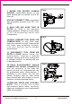
7. NEVER USE OXYGEN, CARBON DIOXIDE, combustible gases or any other bottled gas as a power source for this tool. Fig.4 8.DO NOT CONNECT TOOL to pressure that potentially exceeds 180 PSI (12.3 BAR). 9. ONLY US E AIR HOSE THAT IS R AT E D f or 1 5 0 % o f t h e m a xi mu m system pressure. Please try to use a hose of ID 3/8”connecting nailer with Compressor. . 10.
14. BEFORE USING TOLL, carefully check if there i s any part damaged to obtai n id eal results. D o not use the tool i f th e to o l h a s a n y a i r l e a k e d , uncompleted, damaged parts and n eeds repairing. 15. NEVER USE TOOL if safety, trigge r o r spr in g i s i no perab le , missing o r damaged. Do not alter or remove safety, t ri gg e r o r sp r in g s . Ma k e d a il y inspections for free movement of trigge r and sa fety me chan ism. Fig.7 Fig.8 1 6 .
23. GRIP TOOL FIR MLY TO MAINTAIN CONTR OL while all owing tool to recoil away from w ork surface as fastener is driven. If safety bracket is al lowed to co nta ct wor k su rf ace agai n b ef ore t ri gg e r i s re le a se d , a n un w a n ted fastener will b e fired. 24. DO NOT DRIVE FASTENERS on top of other fasteners, o r with the tool at too steep an an gle: the fasteners can ricochet c ausing persona l injury. Fig.11 Fig.12 25 . D O N O T DR IVE FA ST EN ER S CLOSE to the edge of the workpiece.
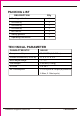
PACKING LIST Q'ty DES CRIPTION Ro ofing coil nailer 1 S5 Hex Key 1 S4 Hex Key 1 S3 Hex Key 1 Air Tool O il 1 Safety glasses 1 O perating instruction 1 TECHNICAL PARAMETER CHARACTERISTIC VALUE Compressed Air pressure 70-120PSI (4.9-8.3bar) Outline Dimension (L×H ×W) 11.5 "× 11.5 "× 5" Nail Length Ran ge 7 Too l Weight 5 .58 Ibs (2.53K g) Air Inlet 1/4 "NP T Air Consumption 0.11ft /cycle at 100psi(at pressu re / 8 "-1 3/ 4 " 3 6.9bar, 3.
FASTENERS SPECIFICATIONS Only use recommended the fasteners. Max . Min. φ0.39 ˝ ( φ10mm) φ0.39 ˝ ( φ10mm) 15 o-16 o 15 o-16 o φ0.12 ˝ ( φ3.05mm) 0.31˝ (8mm) φ0.12 ˝ ( φ3.05mm) 0.31˝ (8mm) OPERATING INSTRUCTIONS FOREWORD It’s a he avy duty, coil fed, pneumatic roofing nailer, u sing 7 3 compressed air as power source. It is designed to install / 8˝-1 / 4˝or Ø 0.12˝ diameter roofing nails of various lengths. It is widely used for connection of roofing frame and conne ction of roofing frame and felt.
C AU T ION : All line co mp o nents (ho ses, co nnectors, filters, regulators, etc.) must meet 150% of the maximum system pressure. Please try to use a hose of ID 3/8”connectingnailer with compressor. Do not connect this tool to a system with maximum potential. Only disconnect quick connector being connected with the connector of the body tail portion air inlet, no compressed air can be guaranteed when disconne cting .
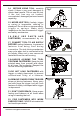
Fig.14 B A Fig.16 Fig .15 Fig .17 A Fig.18 Fig.19 A USING THE TOOL There are two methods of operation to drive nails with theis tool: Contact Fire and Single Sequential Fire (Black trigger) Contact Fire This tool is set u p at the Contact Fire mode 1. P ull the trigger with th e tool off the work piece 2. D epress the safety ag ainst the work piece to drive a nail 3. Move the tool along the work piece with a boun cing motion. Each depression of the safety w ill drive a nail.
Single Seq uential Fire 1. Position the nail outlet on the work piece with finger off the trigger 2. Depres s the safety firmly until it is comple tely depressed. 3. Pull the trigg er to drive a nail 4. Remove fing er from the trigger. To continue nailing in a separate location, move the to ol along the wood, rep eatin g steps 2 - 4 as required. CAUTION : Remove finger from trigger whe n not driving fasteners. Never carry tool with fing er on trigger: tool w ill fire a fastene r if safety is bumped.
CLEARING A JAMMED FASTENER 1. CA UTION: Disconnect tool from air supply . 2.Open latch, rotate lowe r housing and remove the nails of the lowe r housing. 3.Use a slender, s oft steel rod to drive the Fig.21 drive blad e to its uppermost position. U se needle nose pliers to remove the jammed fastener (see Fig.21). 4.Follow instructions in PREPARING THE TOO L BEFO RE DRIV ING to reload fa steners. MAINTENANCE CLEAN AND INSPECT DAILY CA UTION: Disconnect tool from air supply before cleaning and inspection.
SERVICE AND REPAIRS All qu ality tools eventually require servicing of rep lace ment of parts due to we ar from normal use. S ome user servicea ble components are described in the TRO UBLE SHOOTING Section. All repairs made b y local agencies a re fully guaranteed against de fective material and w orkmanship. We cannot guarantee repairs made or attempted b y anyone other than thes e ag encies. Should your have any questions a bout your to ol, please contact with u s at any time.
CAUSE PROBLEM Skipping fasteners/feeding intermittently SOLUT ION 1.Having the foreign matters between the small piston and small cylinder. 2.O-ring on the small piston is worn and damaged. 3.Tool dry and lack lubrication. 4.The spring on the small piston is damaged. 5.Air pressure is lower. 6.Connecting screw of nose and body is loose. 7.Stopped hook can't stop the fasteners. 8.Bent fasteners. 9.Wrong size fasteners. 10.Gasket is damaged. 11.Small piston bumper is worm and damaged. 12.
EXPLODED VIEW DRAWING customerservice@focus-ontools.
PART LIST Item 1 2 3 4 5 6 7 8 9 10 11 12 13 14 15 16 17 18 19 20 21 22 23 24 25 26 27 28 29 30 31 32 33 34 35 36 37 38 39 40 41 42 43 44 45 46 47 48 49 50 51 52 Description Screw M5*20 Bushing Exhaust Cover Washer Screw M5*30 Spring Washer Cylinder Cap Gasket O-ring 36.3*2.5 O-ring 55.4*3 Spring Valve O-ring 40.2*2.3 Cylinder Seal Valve Seat Stopped Washer Washer O-ring 43.3*3.5 Piston Assembly Cylinder O-ring 50.5*2.5 Restrictive plate O-ring 76.36*2 .
Limited Manufacturer Warranty FOT makes every effort to ensure that this product meets high quality and durability standards. FOT warrants to the original retail consumer a 1-year limited warranty from the date the product was purchased at retail and each product is free from defects in materials. Warranty does not apply to defects due directly or indirectly to misuse, abuse, negligence or accidents, repairs or alterations, or a lack of maintenance.