
Manual


VIEWPOINT ALUMINUM RUNNING BOARD
2011-13 DODGE DURANGO
Page 1 of 3 9/5/12 (DP)
Parts List:
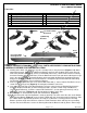
1
Driver/ Left Running Board
12
6mm “T” Bolts
1
Passenger/Right Running Board
12
6-1.0mm x 25mm Hex Bolts
6
Mounting Brackets
24
6mm x 22mm OD x 2mm Large Flat Washers
6
12-1.75mm x 40mm Bolt Plates
12
6mm x 18mm OD x 1.6mm STD Flat Washers
6
12mm Serrated Flange Nuts
12
6mm Lock Washers
6
12mm x 24mm OD x 2.5mm Flat Washers
12
6mm Hex Nuts
6
12mm Plastic Retainers
12
6mm Nylon Lock Nuts
PROCEDURE:
REMOVE CONTENTS FROM BOX. VERIFY ALL PARTS ARE PRESENT. READ INSTRUCTIONS
CAREFULLY BEFORE STARTING INSTALLATION.
1. Starting at the driver side, locate the (3) pairs of factory holes in the pinch weld, (Figure 1 & 2). Move
toward the front pair. Remove the rubber plug filling the oval hole in the bottom of the rocker panel in
front of the two holes, (Figure 3). Select (1) 12mm Bolt Plate and (1) 12mm Plastic Retainer. Partially
thread the Retainer onto the Bolt Plate. Insert the Bolt Plate into the hole and rotate it 90-degrees to go
across the slot, (Figure 4). Thread the Retainer all the way down the Bolt Plate and tight against the
body panel, (Figure 5). NOTE: The Plastic Retainer is designed to prevent the Bolt Plate from falling
into the body cavity and to aid in installing the Bracket.
2. Select (1) Mounting Bracket and secure it to the Bolt Plate with (1) 12mm x 24mm Flat Washer and (1)
12mm Serrated Flange Nut, (Figure 6). Do not tighten hardware at this time.
3. Line up the (2) small slots in the Bracket with the (2) holes in the pinch weld. Bolt the Bracket to the
outside of the pinch weld with (2) 6mm x 25mm Hex Bolts, (2) 6mm x 22mm Large Flat Washers,
(outside against Bracket), (2) 6mm x 18mm STD Flat Washers, (inside against pinch weld), and (2)
6mm Nylon Lock Nuts, (Figures 6 & 7). Do not tighten hardware at this time.
4. Repeat Steps 1 – 3 to install the center and rear Brackets, (Figure 2).
5. Select the driver/left side Running Board. Locate the openings cut at the end of the slots on the bottom
of the Running Board, (Figure 8). Insert (3) 6mm T-Bolts into each channel through the openings. Slide
the T-Bolts into the approximate position in line with the (3) Brackets. Carefully place the Running
Board in position on top of the Brackets. Slide the T-Bolts forward or back until they line up and drop
into the slots on the Brackets. Secure the Running Board to the Brackets with (6) 6mm x 22mm Large
Passenger/Right
Running Board
Driver/Left Running Board
(6) Mounting
Brackets
(6) 12mm x 40mm
Bolt Plates
Front