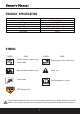
PRODUCT SPECIFICATION Component Motor No-load Speed Cutting Path Height Adjustment Wheels Size Unit Weight Specifications 120 V Ac 60 Hz 12 Amp 3 ,6 0 0 R P M 20 in. (508 mm) 1-3/4–3-3/4 in. (45 mm-95 mm) 7 in. (Front)/ 8 in. (Rear) 26 Kg SYMBOL SYMBOL NAME SYMBOL NAME Serving of toes or fingers-rotary mower blade. Thrown objects from mower deck. Keep bystanders/children away. Safety alert. Slip on slope. Read the operator’s manual. CPSC Danger label.
SAFETY INSTRUCTIONS WARNING: Read all instructions when using electric gardening appliances. Basic safety precautions should always be followed to reduce the risk of fire,electric shock, and personal injury. FOR ALL LAWN MOWERS a) Avoid Dangerous Environment Don’t use appliances in damp or wet locations. b) Don’t Use In Rain. c) Keep Children Away All bystanders (visitors) should be kept at a safe distance from work area. d) Dress Properly Do not wear loose clothing or jewelry.
SAFETY INSTRUCTIONS SAFETY INSTRUCTIONS FOR WALK-BEHIND MOWERS I. GENERAL OPERATION 1. Read, understand, and follow all instructions on the machine and in the manual (s) before starting. 2. Do not put hands or feet near or under the machine. Keep clear of the discharge opening at all times. 3. Only allow responsible adults, who are familiar with the instructions, to operate this machine. 4. Clear the area of objects such as rocks, wire, toys, etc., which could be thrown by the blade.
SAFETY INSTRUCTIONS III. CHILDREN Tragic accidents can occur if the operator is not alert to the presence of children. Children are often attracted to the machine and the mowing activity. Never assume that children will remain where you last saw them. 1. Keep children out of the mowing area and under the watchful care of a responsible adult other than the operator. 2. Be alert and turn mower off if a child enters the area. 3. Never allow children to operate the machine. 4.
SAFETY INSTRUCTIONS • Always wear safety glasses with side shields. Every day glasses have only impact resistant lenses. They are NOT safety glasses. Following this rule will reduce the risk of eye injury. Use face mask if operation is dusty. • Wear eye protection which is marked to comply with ANSI Z87.1 when operating this product.
SAFETY INSTRUCTIONS Double insulated lawn mower This mower is "DOUBLE INSULATED" 1. Replacement Parts: When servicing use only identical replacement parts. 2. Polarized Appliance Connections: To reduce the risk of electric shock, this appliance has a polarized plug (one blade is wider than the other) and will require the use of a polarized extension cord. The appliance plug will fit into a polarized extension cord only one way. If the plug does not fit fully into the extension cord, reverse the plug.
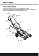
KNOW YOUR PRODUCT Read this owner's manual and safety rules carefully before operating the mower. Compare the illustration below to the mower in order to become familiar yourself with the location of the various controls and adjustments. Save this manual for future reference.
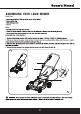
ASSEMBLING YOUR LAWN MOWER Parts List Note: ASSEMBLING THE HANDLE 2 1 3 2 3 8
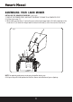
ASSEMBLING YOUR LAWN MOWER INSTALLING THE GRASS CATCHER BAG (see Fig.4) 1. UNPLUG THE POWER CORD, AND WAIT FOR BLADE TO COME TO A COMPLETE STOP. 2. Lift the chute cover (1). 3. While holding up the cover (1), place the grass catcher bag hanger hooks (2) into the opening on the chute cover (1) to allow the hanger hooks to attach to the rod (3) which secures the chute cover. 2 Fig.4 1 3 NOTE: For optimal performance empty grass bag often during use.
ASSEMBLING YOUR LAWN MOWER INSTALL THE SIDE DISCHARGE CHUTE (see Fig.5) This mower has 3different functions -mulch, sidedischarge, andrearbag. If youwish todischarge the clippings rather thanmulch, perform these steps. 1. UNPLUG THE POWER CORD, AND WAIT FOR BLADE TO COME TO A COMPLETE STOP. 2. Lift the side discharge cover (1). 3. Align the grooves on the discharge chute (2) with the pins on the underside of the discharge cover (1). 4.
ASSEMBLING YOUR LAWN MOWER INSTALLATION OR REMOVAL OF THE MULCH PLUG (see Fig.6) 1. UNPLUG THE POWER CORD, AND WAIT FOR BLADE TO COME TO A COMPLETE STOP. 2. To remove the mulch plug lift the chute cover (1) and pull out on the handle. 3. The mulch plug (2) is inserted on an angle so it will require some force when removing. Fig.
ASSEMBLING YOUR LAWN MOWER ADJUST THE UPPER HANDLE HEIGHT (see Fig.7) 1. Loosen the upper handle knob. 2. Adjust the handle to the most comfortable of the 3 positions. 3. Tighten the upper handle knob as tight as you can. Fig.
OPERATING YOUR MOWER ADJUST THE CUTTING HEIGHT ( see Fig.10) 1. Simply depress the lever (1) towards the wheel and move to desired position. This sets all wheels to the same position. 2. To raise the height, pull the height adjustment lever from the current stop position towards the back of the mower. 3. To lower the height, pull the height adjustment lever from the current stop position towards the front of the mower. Fig.10 LOW HIGH 1 7-Position Height Adjustment 1. 2. 3. 4. 5. 6. 7. 1-3/4 in. 2 in.
OPERATING YOUR MOWER WARNING: Do not mow a slope that has an angle of greater than 15° (a rise of approximately2-1/2 ft. [ 75 m]every 10 ft. [3m]).Mow a cross the face of a slope, and never up and down. MOWING TIPS NOTE: A sharp blade will greatly enhance the performance of the mower, especially when cutting high grass. Be sure to check the blade and to sharpen it at least once per year, as described in the Maintenance section operator and to others. clippings.
OPERATING YOUR MOWER Fig.11 Fig.12 Loosen Tighten 1 2 3 NOTE: Be sure to replace the parts in the exact order in which they were removed. When installing the cutting blade, verify that it is installed with the curved ends pointing toward the mower deck. CLEAN THE MOWER WARNING: To reduce the risk of electric shock, do not expose the mower to water. The underside of mower deck should be cleaned after each use as grass clippings, leaves, dirt and other debris will accumulate causing rust and corrosion.
SERVICE 1. When servicing the mower, use only replacement parts that are available from the manufacturer. In order to obtain replacement parts, call the toll-free helpline. The use of parts that do not meet the original equipment specifications may lead to improper performance, and may compromise safety. 2. Before cleaning, repairing, or inspecting, verify that the blade and all moving parts have come to a complete stop, and remove the safety key.
PARTS 18
PARTS LIST APA Part No.
PARTS LIST APA Part No. PM207AC-43-QQ-43 PM207AC-44-QQ-44 PM207AC-45-QQ-45 PM207AC-46-QQ-46 PM207AC-47-QQ-47 PM207AC-48-QQ-48 PM207AC-49-QQ-49 PM207AC-50-QQ-50 PM207AC-51-QQ-51 PM207AC-52-QQ-52 PM207AC-53-QQ-53 PM207AC-54-QQ-54 PM207AC-55-QQ-55 PM207AC-56-QQ-56 PM207AC-57-QQ-57 PM207AC-58-QQ-58 PM207AC-59-QQ-59 PM207AC-60-QQ-60 PM207AC-61-QQ-61 PM207AC-62-QQ-62 PM207AC-63-QQ-63 PM207AC-64-QQ-64 PM207AC-65-QQ-65 PM207AC-66-QQ-66 PM207AC-67-QQ-67 PM207AC-68-QQ-68 Part No.
Steele® warrants to the original purchaser who uses the product in a consumer application (personal, residential or household usage) that all products covered under this warranty are free from defects in material and workmanship for two years from the date of purchase. All products covered by this limited warranty which are used in commercial applications (i.e. income producing) are warranted to be free of defects in material and workmanship for 90 days from the date of original purchase.
Merchandise sold by Steele® which has been manufactured by and identified as the product of another company, such as gasoline engines. The product manufacturer’s warranty, if any, will apply. ANY INCIDENTAL, INDIRECT OR CONSEQUENTIAL LOSS, DAMAGE, OR EXPENSE THAT MAY RESULT FROM ANY DEFECTS, FAILURE OR MALFUNCTION OF THE PRODUCT IS NOT COVERED BY THIS WARRANTY. Some states do not allow the exclusion, so it may not apply to you.