MODELS ST1007, ST1012, ST1014 15" & 20" PLANERS OWNER'S MANUAL (For Models Manufactured Since 9/17) Phone: (360) 734-3482 • Online Technical Support: techsupport@woodstockint.com COPYRIGHT © APRIL, 2016 BY WOODSTOCK INTERNATIONAL, INC. REVISED APRIL, 2019 (JL) #17978MC WARNING: NO PORTION OF THIS MANUAL MAY BE REPRODUCED IN ANY SHAPE OR FORM WITHOUT THE WRITTEN APPROVAL OF WOODSTOCK INTERNATIONAL, INC. V3.04.
This manual provides critical safety instructions on the proper setup, operation, maintenance and service of this machine/equipment. Failure to read, understand and follow the instructions given in this manual may result in serious personal injury, including amputation, electrocution or death. The owner of this machine/equipment is solely responsible for its safe use.
Table of Contents INTRODUCTION..................................................... 2 Contact Info..................................................................... 2 Machine Descriptions.................................................. 2 Manual Accuracy........................................................... 2 Machine Data Sheet..................................................... 3 MACHINE FEATURES.............................................. 5 CONTROLS & COMPONENTS................................
INTRODUCTION Contact Info Manual Accuracy We are committed to customer satisfaction. If you have any questions or need help, use the information below to contact us. We are proud to provide a high-quality owner’s manual with your new machine! IMPORTANT: Before contacting, please get the original purchase receipt, serial number, and manufacture date of your machine. This information is required for all Technical Support calls and it will help us help you faster.
Machine Data Sheet MACHINE SPECIFICATIONS © Woodstock International, Inc. • Phone: (800) 840-8420 • Web: www.woodstockint.com MODEL ST1007, ST1012, & ST1014 PLANERS Model Number ST1007 ST1012 ST1014 640 lbs. 660 lbs. 771 lbs. Product Dimensions Weight Width (side-to-side) x Depth (frontto-back) x Height Foot Print (Length x Width) 42 x 32-1/2 x 46 in. 55-1/2 x 43-1/2 x 46 in. 22-1/2 x 22 in. 23-1/2 x 23-1/2 in. Shipping Dimensions Type Weight Wood Crate 660 lbs.
Model Number ST1007 ST1012 ST1014 Main Specifications Planer Size 15 in. 20 in. Max. Cut Width 15 in. 20 in. Max. Stock Thickness 8 in. Min. Stock Thickness 3/16 in. Min. Stock Length 8 in. 8 in. Number of Cuts Per Inch 42, 63 56, 104 Number of Cuts Per Minute 15,000 8 in. 104, 83 24,000 Cutterhead Speed 4800 RPM Planing Feed Rate 16, 30 RPM Max. Cut Depth Planing Full Width 3/32 in. Max. Cut Depth Planing 6-Inch Wide Board 1/8 in. 1/8 in. Dust Port Size 4 in. 5 in.
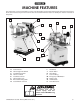
MACHINE FEATURES The instructions in this manual will be easier to understand if you become familiar with the location and names of the basic features of your new machine. Use the list below with the letters to identify the external features of the planer. A B K C J I L D M E G F N O H A. B. C. D. E. F. G. H. Control Panel Table Height Handwheel Feed Roller Gearbox Table Lock Knob Feed Rate Selector Table Height Scale Retractable Lifting Rods Caster Wheel and Lock P I. J. K. L. M. N. O. P.
CONTROLS & COMPONENTS Refer to the Figures 1-3 and the following descriptions to become familiar with the basic controls and components of this machine. Understanding these items and how they work will help you understand the rest of the manual and stay safe when operating this machine. F. Return Rollers: Assist sliding workpiece back to operator following planing operation. G. Dust Port: Connects to a dust collection system to extract shavings and dust during operation.
Internal Components FRONT D C A E REAR F B G Workpiece H H I Figure 4. Workpiece path and major planing components (side cutaway view). A. Anti-Kickback Fingers: Provide additional safety for the operator. B. Serrated Infeed Roller: Pulls the workpiece toward the cutterhead. C. Chip Breaker: Breaks off chips created by the cutterhead to prevent tear out and diverts the chips to the dust hood. D. Chip Deflector: Directs chips into the dust hood. E.
SAFETY For Your Own Safety, Read Instruction Manual Before Operating This Machine The purpose of safety symbols is to attract your attention to possible hazardous conditions. This manual uses a series of symbols and signal words intended to convey the level of importance of the safety messages. The progression of symbols is described below. Remember that safety messages by themselves do not eliminate danger and are not a substitute for proper accident prevention measures.
WEARING PROPER APPAREL. Do not wear clothing, apparel or jewelry that can become entangled in moving parts. Always tie back or cover long hair. Wear non-slip footwear to reduce risk of slipping and losing control or accidentally contacting cutting tool or moving parts. HAZARDOUS DUST. Dust created by machinery operations may cause cancer, birth defects, or longterm respiratory damage. Be aware of dust hazards associated with each workpiece material.
Additional Safety for Planers Serious cuts, amputation, entanglement, or death can occur from contact with rotating cutterhead or other moving components! Flying chips can cause blindness or eye injuries. Workpieces or inserts/ knives thrown by cutterhead can strike nearby operator or bystanders with deadly force. To reduce the risk of these hazards, operator and bystanders MUST completely heed the hazards and warnings below. KICKBACK. Occurs when workpiece is ejected from machine at a high rate of speed.
ELECTRICAL Circuit Requirements Serious personal injury could occur if you connect the machine to the power source before you have completed the set up process. DO NOT connect the machine to the power source until instructed to do so. This machine must be connected to the correct size and type of power supply circuit, or fire or electrical damage may occur. Read through this section to determine if an adequate power supply circuit is available.
Grounding Requirements This machine MUST be grounded. In the event of certain types of malfunctions or breakdowns, grounding provides a path of least resistance for electric current to travel—in order to reduce the risk of electric shock. Improper connection of the equipment-grounding wire will increase the risk of electric shock. The wire with green insulation (with/without yellow stripes) is the equipment-grounding wire.
SETUP This machine presents serious injury hazards to untrained users. Read through this entire manual to become familiar with the controls and operations before starting the machine! UNPLUG-power cord before you do any assembly or adjustment tasks! Otherwise, serious personal injury to you or others may occur!. Items Needed for Setup The following items are needed, but not included, to set up your machine. Description Qty • Additional People........................................................
Inventory A The following is a list of items shipped with your machine. Before beginning setup, lay these items out and inventory them. Note: If you cannot find an item on this list, carefully check around/inside the machine and packaging materials. Often, these items get lost in packaging materials while unpacking or they are pre-installed at the factory. Component Inventory (Figure 7) Qty A. Planer............................................................................... 1 B. Dust Hood.............
Hardware Recognition Chart WASH ASHE H AS E ASHE ASHE ASHE ASHE R ASHE E W R ASHE WASH WA SH H WA S ASHE WASH W W W WASHERS ARE MEASURED BY THE INSIDE DIAMETER R W LINES ARE 1 ⁄16" INCH APART R DIA R DIA W R 5mm 6mm 4mm LINES ARE 1MM APART MEASURE BOLT DIAMETER BY PLACING INSIDE CIRCLE ⁄4" R W 4mm 1 W #10 ⁄16" R DIA M ETE ⁄2" R DIA 5 M ETE 3 1 ⁄8" M ET 23 ⁄4" R DIA M ETE 21 ⁄2" 3 DIA M R ⁄16" ⁄16" R M ETE 7 7 R DIA DIA 12mm ETER 21 ⁄4" DIA
Cleanup The unpainted surfaces of your machine are coated with a heavy-duty rust preventative that prevents corrosion during shipment and storage. This rust preventative works extremely well, but it will take a little time to clean. Be patient and do a thorough job cleaning your machine. The time you spend doing this now will give you a better appreciation for the proper care of your machine's unpainted surfaces.
Site Considerations Weight Load Physical Environment Refer to the Machine Specifications for the weight of your machine. Make sure that the surface upon which the machine is placed will bear the weight of the machine, additional equipment that may be installed on the machine, and the heaviest workpiece that will be used. Additionally, consider the weight of the operator and any dynamic loading that may occur when operating the machine.
Lifting & Moving 2. Remove the pin and hex bolt that are already mounted in the foot pedal bracket. The planer is equipped with four lifting bars that extend in order to lift and place the planer, as shown in Figure 10. 3. Align the caster assembly with the mounting holes in the foot pedal bracket. 4. Insert the hex bolt into the hole in the back side of the caster assembly, and tighten the bolt just enough for it to be snug without hampering the pivot action of the caster. 5.
Assembly 4. With a helper, match the tapped holes on the side of the table to the cast iron wings and lightly secure the wings in place with the (3) M8-1.25 x 30 hex bolts and the 8mm lock and flat washers (for the ST1014 use (3) M8-1.25 x 35 hex bolts). 5. Place a straightedge flat across the table and across the wings, as shown in Figure 14. The cast-iron extension wings are identical for both the infeed and the outfeed ends of the table. To assemble planer: 1.
9. Place the bushing on the handwheel shaft and insert the key into the shaft keyway. 10. Screw the handle into the handwheel, place the handwheel on the shaft and secure it with the hex nut and flat washer, as shown in Figure 15. This machine creates substantial amounts of dust during operation. Breathing airborne dust on a regular basis can result in permanent respiratory illness. Reduce your risk by wearing a respirator and capturing the dust with a dust collection system.
18. Loosen the eccentric set screws; as shown in Figure 18. 21. Wipe dirt from the gearbox fill plug and remove it (see Figure 20). —If the oil runs out, the gearbox is full, and re-install the plug. Set Screw Eccentric —If the oil does not run out, fill the gearbox until it does, and re-install the plug. Note: Replace the gearbox oil after the first 20 hours of operation. This is a normal break-in procedure. Figure 18. Roller set screws. 19.
Test Run Once assembly is complete, test run the machine to ensure it is properly connected to power and safety components are functioning correctly. If you find an unusual problem during the test run, immediately stop the machine, disconnect it from power, and fix the problem BEFORE operating the machine again. The Troubleshooting table in the SERVICE section of this manual can help. 5. Press START button to turn machine ON. Verify motor starts up and runs smoothly without any unusual problems or noises.
OPERATIONS Eye injuries or respiratory problems can occur while operating this tool. Wear personal protective equipment to reduce your risk from these hazards. The overview below provides the novice machine operator with a basic understanding of how the machine is used during operation, so the machine controls/components discussed later in this manual are easier to understand. Due to its generic nature, this overview is NOT intended to be an instructional guide.
Workpiece Inspection Wood Types Some workpieces are not safe to use or may require modification before they are. Before cutting, inspect all workpieces for the following: The species of wood, as well as its condition, greatly affects the depth of cut the planer can effectively take with each pass.
Planing Tips • Inspect your lumber for twisting or cupping, and surface one face on a jointer if necessary before planing workpiece. • Scrape off all glue when planing glued-up panels. Dried glue can quickly dull knives/inserts. • DO NOT plane more than one piece at a time. • Never remove more than the recommended amount of material on each pass. Only remove a small amount of material on each pass when planing wide or dense stock. • Support the workpiece on both ends.
Pitch & Glue Build-up Problem: Glue and resin buildup on the rollers and cutterhead will cause overheating by decreasing cutting sharpness while increasing drag in the feed mechanism. The result can include scorched lumber, uneven knife/insert marks, and chatter. Solution: Clean the rollers and cutterhead. Chip Marks or Indentations Problem: Chip indentation or chip bruising is the result of wood chips not being thrown away from the cutterhead and out of the machine.
Bed Roller Height Bed Roller Height Range........................... 0.002"–0.020" The correct height of the bed rollers will vary, depending on the type of material you intend to plane. However, as a general rule, keep the bed roller height within 0.002"–0.020" above the table surface, as illustrated in Figure 24. Tools Needed Qty Hex Wrench 4mm (ST1007, ST1012).............................. 1 Hex Wrench 3mm (ST1014)............................................... 1 Hex Wrench 6mm..........................
Setting Feed Rate The infeed and outfeed rollers move the workpiece through the planer while keeping it flat and providing a consistent rate of movement. The speed that these rollers move the workpiece through the planer is the feed rate. Generally, low feed rates are used for dimensioning passes, while higher feed rates are used for finishing passes.
The cutterhead for the Model ST1007 ships with both springs and jack screws for adjusting the knife height (see Figure 27). Which one you use is a matter of personal preference. Springs exert upward pressure from underneath the knives and allow adjustments to be made very quickly. Jack screws support the knives from underneath, and by threading the screws in or out, you can precisely control the knife height. In both instances, wedge-type gibs and gib bolts lock the knives in place.
7. Rotating/Replacing Cutterhead Inserts (ST1012/ST1014) Slightly tighten gib bolts, starting at middle and working your way to ends by alternating left and right, as illustrated in Figure 30. 5 3 1 2 4 Figure 30. Gib bolt tightening sequence. 7. Repeat Step 6, tightening gib bolts a little more. 8. Repeat Steps 4–8 for remaining knives. 9. Fully tighten all gib bolts in sequence shown in Figure 30 for each knife.
4. Remove any sawdust or debris from head of insert, Torx screw, and surrounding area (see Figure 32). 6. —If all four insert cutting edges have been used, replace insert with a new one. Always position insert reference dot in same position when installing a new insert to aid in rotational sequencing. Torx Screw 7. Cutterhead Insert Figure 32. Example of cutterhead inserts and Torx screws (actual machine not shown). 5. Replace insert so that a fresh cutting edge faces outward.
ACCESSORIES The following lathe accessories may be available through your local Woodstock International Inc. Dealer. If you do not have a dealer in your area, these products are also available through online dealers. Please call or e-mail Woodstock International Inc. Customer Service to get a current listing of dealers at: 1-800-545-8420 or at sales@ woodstockint.com.
The D3635 15" Planer Blades fit our Steelex ST1007 planer. Made from high-speed steel, these knives are sold as a set of 3. The Model D4042 6" Digital Caliper lets you switch between decimal and fractional inches and millimeters. Large digital readout makes precision measurements easy with a resolution of 0.0005". Features include hardened stainless-steel jaws and beam, thumb roll, lock knob, zero reset button, and an absolute and relative measurement function. Figure 37. Model D3635 15" Planer Blades.
The D4028 8" Digital Scale provides precise relative distance measurements between fixed and moving parts within an 8" and 12" range. Ideal for mounting to woodworking and metalworking machines for table height adjustments, cutter heights, depth adjustments and more. Resolution is 0.01mm and maximum measuring speed is 1.5m/s. Features inches and millimeters conversion button, plus and minus preset buttons and zero setting on button. Each Digital Scale includes an extra long life battery.
MAINTENANCE Schedule To reduce risk of shock or accidental startup, always disconnect machine from power before adjustments, maintenance, or service. General Regular periodic maintenance on your STEELEX® Model ST1007/ST1012/ST1014 will ensure its optimum performance. Make a habit of inspecting your machine each time you use it. Check for the following conditions and repair or replace when necessary: • • • • • Loose mounting bolts. Worn switch. Worn or damaged cords and plugs. Damaged V-belt.
Basic Adjustment Tools We have provided a jig to make the knife setting process easy and quick. Please refer to Figure 43 for jig component identification while assembling. Optional Adjustment Tools To assemble the knife setting jig: To make the setup process easier and more accurate, many woodworkers purchase optional aftermarket products like the Rotacator® and the Planer Pal®. 1. Snap one of the E-clips over the notch on one end of the knife setting rod. • 2.
Lubrication Grease Since all bearings are sealed and permanently lubricated, leave them alone until they need to be replaced. Do not lubricate them. Oil The Model ST1007/ST1012/ST1014 does need lubrication in other places. • • Columns and Leadscrews: Lubricate columns weekly with light oil, and lubricate the four leadscrews once a month with general purpose grease. Worm Gear: Inspect the worm gear monthly and lubricate when needed.
Tensioning/Replacing V-Belts Tools Needed Qty Phillips Screwdriver.............................................................. 1 Open-End Wrench 19mm.................................................. 1 To tension/replace V-belts: After approximately 16 hours of operation, V-belts will stretch and seat into pulley grooves and need to be properly tensioned to avoid severely reducing life of V-belts. 1. DISCONNECT MACHINE FROM POWER! 2.
4. 5. If V-belts need to be replaced, raise motor to release belt tension (see next step for instructions), roll them off pulleys, then replace with a matched set of 3. Anti-Kickback Pawls To adjust V-belt tension, loosen both top motor mount hex nuts (see Figure 50 on Page 38), then adjust bottom hex nuts to raise or lower motor. The Model ST1007/ST1012/ST1014 features anti-kickback pawls (shown in Figure 52) as an important safety feature.
SERVICE Troubleshooting The following troubleshooting tables cover common problems that may occur with this machine. If you need replacement parts or additional troubleshooting help, contact our Technical Support. Note: Before contacting Tech Support, find the machine serial number and manufacture date, and if available, your original purchase receipt. This information is required to properly assist you. Motor & Electrical PROBLEM POSSIBLE CAUSE CORRECTIVE ACTION 1. Rotate button head to reset.
Machine Operation PROBLEM POSSIBLE CAUSE CORRECTIVE ACTION Excessive snipe (gouge in end of board that is uneven with rest of cut). Note: A small amount of snipe is inevitable with all types of planers. The key is minimizing it as much as possible. 1. Lower bed rollers (Page 27). 1. One or both of bed rollers are set too high. 2. Outfeed extension slopes down or is not level 2. Shim outfeed extension wing level with main table. with main table. 3. Raise height of chipbreaker or pressure bar (Page 42).
Adjusting Feed Rollers, Chip Breaker & Pressure Bar It is essential that the feed rollers, chip breaker, and pressure bar (see Figure 53) are set at the correct distance below the cutterhead knives/inserts at BDC (bottom dead center) to ensure that the workpiece moves through the planer evenly and the correct distance from the cutterhead knives/inserts. Chip Breaker BDC (Bottom Dead Center) Using a Rotacator Tools Needed Qty Phillip's Screwdriver #2.......................................................
6. Rotate the cutterhead with the V-belt pulley so one of the knives is at BDC as shown in Figure 54. 7. Use your Rotacator to find bottom dead center (BDC) of any knife/insert edge by slowly rocking cutterhead pulley back and forth, then set Rotacator dial to "0" (see Figure 54). 8. Keeping Rotacator dial at "0", position it under right-hand side of infeed roller (see Figure 54) and find BDC of a serrated edge. 10. Repeat Steps 8–9 on left-hand side of infeed roller. 11.
14. Repeat Step 12 for pressure bar height adjustment. The adjustment controls are shown in Figure 57. 15. Re-install belt cover, top cover, drive chain cover, and dust hood. 3. DISCONNECT MACHINE FROM POWER! 4. Lower bed rollers below table surface (refer to Bed Roller Height on Page 27 for detailed instructions). 5. Place wood blocks along sides of table, as illustrated in Figure 58. Adjustment Jam Nut & Set Screw Figure 57. Example of adjusting the pressure bar height.
10. Loosen jam nuts and set screws on each side of infeed roller (see Figure 59). 11. Using a feeler gauge, adjust set screw so it is 0.040" from roller bushing block (see Figure 59), then tighten jam nut. Repeat on other side of infeed roller. 15. Repeat Steps 13–14 for pressure bar height adjustment, but adjust the gap to 0.040" (see Figure 61). Jam Nut & Set Screw Roller Bushing Block Insert Feeler Gauge Here Insert Feeler Gauge Here Figure 61.
Adjusting Roller Spring Tension The infeed and outfeed rollers keep the workpiece moving through the planer. There are springs that exert downward pressure on the rollers while still allowing them to raise with an uneven workpiece surface. Proper roller spring tension is crucial to keep the workpiece moving through the planer during operation. Roller spring tension will vary depending upon the type of wood you are planing.
Positioning Chip Deflector Adjusting Table Parallelism When properly distanced from the cutterhead, the chip deflector directs the chips into the dust hood, and keeps them from falling onto the outfeed roller and being pressed into the workpiece. Tools Needed Qty Phillips Screwdriver #2........................................................ 1 Hex Wrench 6mm.................................................................. 1 Chip Deflector Gap Setting...........................................
5. Place the block under the front of the head casting, to either side of the depth limiter tab. Raise the table up so the block barely touches the head casting as shown in Figure 66. To adjust table more than 0.016": 1. Remove the side cabinet plate. 2. On the underside of the table there is a chain drive and five sprockets as shown in Figure 67. The four sprockets in the corners control the movement of the table columns. The fifth sprocket is the idler sprocket that controls the chain tension.
Calibrating Table Height Scale To adjust table less than 0.016": 1. Use the table mounting screws shown in Figure 69. Loosen the screws and lift/lower the table until the table and the cutterhead body are parallel with each other and the table is parallel with the head casting from front to back. This may require some trial and error. Although correctly set at the factory, the table height scale can be adjusted for accuracy if it becomes necessary. Tools Needed............................................
Aligning Pulleys —If pulleys are not parallel, loosen four motor mount hex nuts (see Figure 72), shift motor on its mount until pulleys are parallel, then re-tighten motor mount hex nuts. Proper pulley alignment prevents premature V-belt wear and unnecessary load on the motor. It also ensures efficient and effective transfer of power. The pulleys are properly aligned when they are parallel and in the same plane as each other. Tools Needed Qty Straightedge 3'................................................
ST1007 & ST1012 Electrical Components Start Capacitor Start Button Stop Button Control Box Run Capacitor Power Lamp Figure 73. ST1007 & ST1012 control panel. Figure 74. ST1007 & ST1012 capacitors. Motor Contactor Motor Capacitors Inside Motor Thermal Relay Figure 75. ST1007 & ST1012 magnetic switch assembly. ST1007/12/14 15" & 20" Planers (Mfd.
ST1007 Wiring Diagram CONTROL PANEL (from Behind) Control Box START POWER STOP Ground Ground G Hot 240 VAC Hot 6-20 Plug 240V A1 3L2 Contactor 1L1 MAGNETIC SWITCH ASSY 13NO NHD C-09D 2T1 4T2 14NO 6T3 A2 NHD NTH-21 17 21 Thermal Overload Relay 5L3 98 2T1 R O 18 20 97 96 4T2 Ground 95 6T3 Run Capacitor 20MFD 450VAC Start Capacitor 200MFD 250VAC MOTOR (240V, Single-Phase) -52- ST1007/12/14 15" & 20" Planers (Mfd.
ST1012 Wiring Diagram CONTROL PANEL (from Behind) Control Box START POWER STOP Ground Ground G Hot 240 VAC Hot 6-20 Plug 240V A1 3L2 Contactor 1L1 MAGNETIC SWITCH ASSY 13NO NHD C-09D 2T1 4T2 14NO 6T3 A2 NHD NTH-21 17 21 Thermal Overload Relay 5L3 98 2T1 R O 18 20 97 96 4T2 Ground 95 6T3 Run Capacitor 40MFD 450VAC Start Capacitor 250MFD 250VAC MOTOR (240V, Single-Phase) ST1007/12/14 15" & 20" Planers (Mfd.
ST1014 Electrical Components Figure 76. Motor junction box. Figure 77. Capacitors. Start Power Stop Figure 78. ST1014 control panel (viewed from behind). -54- Figure 79. ST1014 magnetic switch assembly. ST1007/12/14 15" & 20" Planers (Mfd.
ST1014 Wiring Diagram CONTROL PANEL (viewed from behind) Control Box POWER START Wt STOP Rd Bk Rd COLOR KEY Rd Ground Rd Rd Gn Rd Rd Bl Rd Rd BLACK Bk WHITE Wt GREEN Gn RED Rd BLUE Bl Rd Gn Bl Wt Ground Rd Bk Wt Bl Gn Gn Wt Rd Bk Wt G Y Gn Gn Wt Bk L6-30 PLUG Hot 240 VAC Bk Rd Rd Bk A1 1L1 Contactor X Hot 3L2 5L3 Bl Gn 13NO GROUND 17 NHD C-35D 18 2T1 4T2 14NO 6T3 A2 28 32 NHD NTH-32 26 Thermal Overload Relay Rd R O 1 30 3 Rd Rd 98 2T1 Bk
ST1007/ST1012 PARTS ST1007 Main Breakdown 30-7 30-8 30-9 30-10 30-1 30-6 30-3 30-2 82 83 84 77 30-4 78 79 30-5 80 30 36 44 56 54 45 27 63 60 45 62 42 57 7 70 71 69 68 75 5 2 6 11 8 9 10 15 14 16 1 67 74 72-1 72-4 47 72 21 22 24 20 72-3 72-2 19 18 12 49 48 72 73 25 4 3 52 53 43 27 61 38 39 51 55 64 46 76 50 41 66 65 59 58 35 37 26 17 14 23 13 -56- ST1007/12/14 15" & 20" Planers (Mfd.
ST1007/ST1012 Main Parts List REF PART # DESCRIPTION REF PART # DESCRIPTION 1 2 3 4 5 6 7 8 9 10 11 12 13 14 15 16 17 18 19 20 21 22 23 24 25 26 27 35 36 37 38 39 41 42 43 44 45 46 47 48 RUBBER FOOT RELIEF BUSHING UNIVERSAL WHEEL HEX NUT M8-1.25 FLAT WASHER 8MM HEX BOLT M8-1.25 X 65 REAR WHEEL SLEEVE EXT RETAINING RING 9MM FLAT WASHER 12MM SHAFT 12MM FOOT PEDAL HEX NUT M8-1.25 HEX BOLT M8-1.25 X 100 FLAT WASHER 8MM HEX BOLT M8-1.
ST1007/ST1012 Headstock Parts Diagram 102 103 109 112 119 121 124 120 114 115 113 125 123 122 140 166 139 142 141 126 145 193 199 194 195 116 197 177 198 186 117 162 111 108 110 112 106 107 129 127 131 134 133 135 130 173 138 132 137 136 155 156 151 165 159 154 152 153 158 157 167 160 164 161 163V2 165 ST1007 Parts 177-1 147 169 170 171 168 146 150 128 149 182 175 ST1012 Parts 200-1 200-2 179 172 178 189 191 181 145 144 143 148 196 176 174 180 101 105 185 183 184 18
ST1007/ST1012 Headstock Parts List REF PART # DESCRIPTION REF PART # DESCRIPTION 101 102 103 104 105 106 107 108 109 110 111 112 113 114 115 116 117 118 119 120 121 122 123 124 125 126 127 128 129 130 131 132 133 134 135 136 137 138 139 140 141 142 143 144 145 146 147 148 149 150 151 152 XST1007101 XST1007102 XST1007103 XST1007104 XST1007105 XST1007106 XST1007107 XST1007108 XST1007109 XST1007110 XST1007111 XST1007112 XST1007113 XST1007114 XST1007115 XST1007116 XST1007117 XST1007118 XST1007119 XST1007
ST1007/ST1012 Gearbox Diagram & Parts List 201 242 241 240 202 234 209 211 208 205 204 203 210 227 229 215 221 222 228 206 207 233 214 212 213 216 218 239 226 217 230 219 223 224 231 232 235 225 220 237 236 238 REF PART # DESCRIPTION REF PART # DESCRIPTION 201 202 203 204 205 206 207 208 209 210 211 212 213 214 215 216 217 218 219 220 221 222 GEARBOX COVER HEX BOLT M6-1 X 25 SPROCKET FLAT WASHER 8MM HEX BOLT M8-1.25 X 16 CHAIN 06B-1 X 51 ROUND KNOB M8-1.
ST1007/ST1012 Lower Table Diagram & Parts List 318 308 305 316 315 311 327 314 313 317 312 320 333 304 303 310 306 307 319 328 329 303 325 321 322 302 326 323 324 309 301 REF PART # DESCRIPTION REF PART # DESCRIPTION 301 302 303 304 305 306 307 308 309 310 311 312 313 314 315 CHAIN 12.7A X 134 HEX BOLT M12-.175 X 45 FLAT WASHER 12MM LIFTING BAR COLUMN BALL BEARING 6302ZZ INT RETAINING RING 42MM DRIVE COLUMN SPROCKET SET SCREW M10-1.
ST1007/ST1012 Upper Table Diagram & Parts List 420 419 408 409 411 417 418 412 413 414 416 415 408 409 410 407 413 411 401 410 405 406 404 REF PART # DESCRIPTION REF PART # DESCRIPTION 401 404 405 406 407 408 409 410 411 XST1007401 XST1007404 XST1007405 XST1007406 XST1007407 XST1007408 XST1007409 XST1007410 XST1007411 SET SCREW M8-1.25 X 20 HEX BOLT M8-1.25 X 30 FLAT WASHER 8MM LOCK WASHER 8MM EXTENSION WING KNOB M12-1.
ST007/ST1012 Label Placement (02/17/16) • Labels must be made of chemical-resistant material EYE/EAR/LUNG INJURY HAZARD! ACCIDENTAL INJURY HAZARD! Always wear safety glasses, ear protection, and respirator when using this machine. Disconnect power supply before adjustments, setup or maintenance! READ and UNDERSTAND MANUAL to avoid serious injury! If a manual is not available, DO NOT use machine! Instead, go to www.shopfox.biz or call (360) 734-3482.
ST1014 PARTS ST1014 Headstock Breakdown 3 6 12 9 8 11 5 10 15 14 13 22 26 31-2 31-3 38 39 41 31-1 33 31 71 27 40 37 45 44 46 47 32 36 35 105 93 108 65 67 110 109 64 59 69 52 54 53 55 57 58 62 72 86 68V2 82 82 87 88 77 84 75 76 103 111 29 50 48 73 74 114 30 60 56 61 70 63 66 51 34 43 42 24 28 78 101 102 100 104 106 112 1 7 20 19 21 23 2 80 83 81 107 79 92 85 91 98 96 94 85-1 90 89 97 95 99 -64- ST1007/12/14 15" & 20" Planers (Mfd.
ST1014 Headstock Parts List REF PART # DESCRIPTION REF PART # DESCRIPTION 1 2 3 5 6 7 8 9 10 11 12 13 14 15 19 20 21 22 23 24 26 27 28 29 30 31 31-1 31-2 31-3 32 33 34 35 36 37 38 39 40 41 42 43 44 45 46 47 48 50 51 52 HANDLE HEX NUT M12-1.
ST1014 Headstock Parts List Continued REF PART # DESCRIPTION REF PART # DESCRIPTION 101 102 103 104 105 106 107 XST1014101 XST1014102 XST1014103 XST1014104 XST1014105 XST1014106 XST1014107 FLAT WASHER 6MM CUTTERHEAD PULLEY MOTOR PULLEY FLAT WASHER 8MM HEX BOLT M8-1.25 X 25 BELT GUARD FLANGE BOLT M6-1 X 10 108 109 110 111 112 114 XST1014108 XST1014109 XST1014110 XST1014111 XST1014112 XST1014114 BELT COVER STAND-OFF FLAT WASHER 8MM HEX NUT M8-1.25 COGGED V-BELT MX-60 BELT COVER STAR KNOB M8-1.
ST1014 Gearbox Breakdown and Parts List 201 202 234 209 205 211 208 204 203 210 227 221 222 229 228 215 207 214 233 212 206 213 216 218 239 226 217 225 230 231 232 223 219 236 220 237 224 238 235 REF PART # DESCRIPTION REF PART # DESCRIPTION 201 202 203 204 205 206 207 208 209 210 211 212 213 214 215 216 217 218 219 220 GEAR BOX COVER CAP SCREW M6-1 X 25 SPROCKET FLAT WASHER 8MM HEX BOLT M8-1.25 X 16 CHAIN 06B-1 X 51 BALL KNOB M10-1.
ST1014 Cabinet Breakdown 372 373 374 368 317-1 369 370 371 317-7 317-4 317-2 317-9 302 303 317-5 317-3 317-6 317-8 317-10 350-3 317 350-1 315 306 350 350-2 350-4 310 362 309 363 364 322 351 316 313 318 320 305 314 312 304 308 307 361 360 319 365 366 359 358 321 354 355 323 326 325 324 327 357 356 301 311 329 367 352 353 328 349 348 347 346 330 345 331 344 343 332 342 341 333 340 334 338 335 337 339 336 -68- ST1007/12/14 15" & 20" Planers (Mfd.
ST1014 Cabinet Parts List REF PART # DESCRIPTION REF PART # DESCRIPTION 301 302 303 304 305 306 307 308 309 310 311 312 313 314 315 316 317 317-1 317-2 317-3 317-4 317-5 317-6 317-7 317-8 317-9 317-10 318 319 320 321 322 323 324 325 326 327 328 329 330 331 332 333 334 XST1014301 XST1014302 XST1014303 XST1014304 XST1014305 XST1014306 XST1014307 XST1014308 XST1014309 XST1014310 XST1014311 XST1014312 XST1014313 XST1014314 XST1014315 XST1014316 XST1014317 XST1014317-1 XST1014317-2 XST1014317-3 XST1014317
ST1014 Table Breakdown and Parts List 407 409 408 405 404 403 402 406 401 410 408 414 412 406 411 413 REF PART # DESCRIPTION REF PART # DESCRIPTION 401 402 403 404 405 406 407 MAIN TABLE BED ROLLER BALL BEARING 6201 ECCENTRIC SHAFT SET SCREW M6-1 X 12 LOCK BAR GIB 408 409 410 411 412 413 414 LOCKING ROD STAR KNOB M12-1.75 EXTENSION WING LOCK WASHER 8MM FLAT WASHER 8MM HEX BOLT M8-1.25 X 35 SET SCREW M8-1.
ST1014 Columns Breakdown and Parts List 518 516 515 509 511 505 508 514 513 505 511 517 505 511 512 520 532 531 530 501 510 502 506 507 504 523 519 503 528 529 527 521 522 525 526 524 533 REF PART # DESCRIPTION REF PART # DESCRIPTION 501 502 503 504 505 506 507 508 509 510 511 512 513 514 515 516 517 BASE HEX BOLT M12-1.75 X 60 HEX NUT M12-1.75 FLAT WASHER 12MM COLUMN BALL BEARING 6202ZZ INT RETAINING RING 35MM DRIVE COLUMN INT RETAINING RING 38MM SET SCREW M10-1.
ST1014 Label Placement Safety labels warn about machine hazards and ways to prevent injury. The owner of this machine MUST maintain the original location and readability of the labels on the machine. If any label is removed or becomes unreadable, REPLACE that label before using the machine again. Contact Woodstock International, Inc. at (360) 734-3482 or www.shopfoxtools.com to order new labels.
ST1007/12/14 15" & 20" Planers (Mfd.
WARRANTY Woodstock International, Inc. warrants all STEELEX® machinery to be free of defects from workmanship and materials for a period of two years from the date of original purchase by the original owner. This warranty does not apply to defects due directly or indirectly to misuse, abuse, negligence or accidents, lack of maintenance, or reimbursement of third party expenses incurred. Woodstock International, Inc.
Warranty Registration Name________________________________________________________________________________________ Street________________________________________________________________________________________ City___________________________ State______________________________Zip__________________________ Phone #________________________ Email_____________________________Invoice #_____________________ Model #_________Serial #______________Dealer Name__________________Purchase Date___________ The following in
FOLD ALONG DOTTED LINE Place Stamp Here WOODSTOCK INTERNATIONAL INC. P.O.