MODEL ST1006/ST1011 8" JOINTER OWNER'S MANUAL (For Models Manufactured since 03/16) Phone: (360) 734-3482 • Online Technical Support: tech-support@shopfox.biz COPYRIGHT © APRIL, 2016 BY WOODSTOCK INTERNATIONAL, INC., REVISED JUNE, 2018 (HE) WARNING: NO PORTION OF THIS MANUAL MAY BE REPRODUCED IN ANY SHAPE OR FORM WITHOUT THE WRITTEN APPROVAL OF WOODSTOCK INTERNATIONAL, INC. #17979MC Printed in China V2.06.
This manual provides critical safety instructions on the proper setup, operation, maintenance and service of this machine/equipment. Failure to read, understand and follow the instructions given in this manual may result in serious personal injury, including amputation, electrocution or death. The owner of this machine/equipment is solely responsible for its safe use.
Table of Contents INTRODUCTION..................................................... 2 Contact Info..................................................................... 2 Machine Descriptions.................................................. 2 Manual Accuracy........................................................... 2 Model ST1006 Specifcations..................................... 3 Model ST1011 Specifications.................................... 5 Identification..............................................
INTRODUCTION Contact Info Manual Accuracy We are committed to customer satisfaction. If you have any questions or need help, use the information below to contact us. We are proud to provide a high-quality owner’s manual with your new machine! IMPORTANT: Before contacting, please get the original purchase receipt, serial number, and manufacture date of your machine. This information is required for all Technical Support calls and it will help us help you faster.
MACHINE SPECIFICATIONS © Woodstock International, Inc. • Phone: (800) 840-8420 • Web: www.woodstockint.com MODEL ST1006 8" JOINTER WITH ADJUSTABLE BEDS Product Dimensions: Weight ..................................................................................................................................................................................................................... 510 lbs. Length x Width x Height .....................................................................................
Main Specifications: Operation Bevel Jointing .............................................................................................................................................................................0 – 45 deg. L/R Maximum Width of Cut ............................................................................................................................................................................... 8 in. Maximum Depth of Cut .....................................................
MACHINE SPECIFICATIONS © Woodstock International, Inc. • Phone: (800) 840-8420 • Web: www.woodstockint.com MODEL ST1011 8" JOINTER WITH MOBILE BASE Product Dimensions: Weight ..................................................................................................................................................................................................................... 508 lbs. Length x Width x Height .........................................................................................
Main Specifications: Operation Bevel Jointing .............................................................................................................................................................................0 – 45 deg. L/R Maximum Width of Cut ............................................................................................................................................................................... 8 in. Maximum Depth of Cut .....................................................
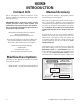
Machine Features The instructions in this manual will be easier to understand if you become familiar with the location and names of the basic features of your new machine. Use the list below with the letters in Figure 1 and Figure 2 to identify the 8" jointer feature locations. B D C E A F G H L J I K Figure 1. Front view of machine. A. B. C. D. E. F. G. H. I. J. K. L. M. N.
Controls & Components This section covers the basic controls used during routine operations. STOP Button: Stops motor when pushed in and disables the START button. Enable the START button by twisting the STOP button until it springs forward in the out position. START Button: Starts motor only if the STOP button is in the out position (see Figure 3). The outfeed table is preset with positive stops, so no range of movement is allowed (if it gets accidentally unlocked it will not move).
SAFETY For Your Own Safety, Read Instruction Manual Before Operating This Machine The purpose of safety symbols is to attract your attention to possible hazardous conditions. This manual uses a series of symbols and signal words intended to convey the level of importance of the safety messages. The progression of symbols is described below. Remember that safety messages by themselves do not eliminate danger and are not a substitute for proper accident prevention measures.
WEARING PROPER APPAREL. Do not wear clothing, apparel or jewelry that can become entangled in moving parts. Always tie back or cover long hair. Wear non-slip footwear to reduce risk of slipping and losing control or accidentally contacting cutting tool or moving parts. HAZARDOUS DUST. Dust created by machinery operations may cause cancer, birth defects, or longterm respiratory damage. Be aware of dust hazards associated with each workpiece material.
Additional Safety for Jointers Serious cuts, amputation, entanglement, or death can occur from contact with rotating cutterhead or other moving components! Flying chips can cause blindness or eye injuries. Workpieces or inserts/ knives thrown by cutterhead can strike nearby operator or bystanders with deadly force. To reduce the risk of these hazards, operator and bystanders MUST completely heed the hazards and warnings below. KICKBACK. Occurs when workpiece is ejected from machine at a high rate of speed.
ELECTRICAL Circuit Requirements Serious personal injury could occur if you connect the machine to the power source before you have completed the set up process. DO NOT connect the machine to the power source until instructed to do so. This machine must be connected to the correct size and type of power supply circuit, or fire or electrical damage may occur. Read through this section to determine if an adequate power supply circuit is available.
Grounding Requirements This machine MUST be grounded. In the event of certain types of malfunctions or breakdowns, grounding provides a path of least resistance for electric current to travel—in order to reduce the risk of electric shock. Improper connection of the equipment-grounding wire will increase the risk of electric shock. The wire with green insulation (with/without yellow stripes) is the equipment-grounding wire.
SETUP Unpacking The Model ST1006/ST1011 was carefully packed when it left our warehouse. If you discover your machine is damaged immediately call your dealer. Save the containers and all packing materials for possible inspection by the carrier or its agent. Otherwise, filing a freight claim can be difficult. When you are completely satisfied with the condition of your shipment, you should inventory the contents.
Inventory A The following is a list of items shipped with your machine. Before beginning setup, lay these items out and inventory them. Note: If you cannot find an item on this list, carefully check around/inside the machine and packaging materials. Often, these items get lost in packaging materials while unpacking or they are pre-installed at the factory. E D F G NOTICE Cardboard Box (Figure 8) Qty L. Stand Assembly w/Motor......................................... 1 M. Pedestal Switch...............
Hardware Recognition Chart WASH ASHE H AS E ASHE ASHE ASHE ASHE R ASHE E W R ASHE WASH WA SH H WA S ASHE WASH W W W WASHERS ARE MEASURED BY THE INSIDE DIAMETER R DIA R W LINES ARE 1 ⁄16" INCH APART ⁄4" R DIA W R 4mm 1 5mm R W 6mm 4mm LINES ARE 1MM APART MEASURE BOLT DIAMETER BY PLACING INSIDE CIRCLE ⁄16" W #10 R DIA 5 R DIA M ETE ⁄2" ⁄8" DIA M M ETE 3 1 3 M ET 23 ⁄4" R DIA M ETE 21 ⁄2" ⁄16" R R ⁄16" W 7 7 R DIA M ETE 21 ⁄4" DIA DIA 12mm E
Cleanup The unpainted surfaces of your machine are coated with a heavy-duty rust preventative that prevents corrosion during shipment and storage. This rust preventative works extremely well, but it will take a little time to clean. Be patient and do a thorough job cleaning your machine. The time you spend doing this now will give you a better appreciation for the proper care of your machine's unpainted surfaces.
Site Considerations Weight Load Physical Environment Refer to the Machine Specifications for the weight of your machine. Make sure that the surface upon which the machine is placed will bear the weight of the machine, additional equipment that may be installed on the machine, and the heaviest workpiece that will be used. Additionally, consider the weight of the operator and any dynamic loading that may occur when operating the machine.
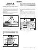
Assembly 4. Turn the stand rightside up and remove the back cover. To assemble jointer: 1. Carefully lay the stand on its side. 2. Use (1) M8-1.25 x 50 hex bolt and (1) 8mm flat washer to bolt the wheel assembly to the stand, as shown in Figure 10. The jointer is very heavy. The next step requires 4 strong people or power lifting equipment to lift the jointer. 5. With assistance, lift the jointer onto the stand and align the mounting holes. 6. Use (8) M8-1.
8. Put the V-belt on motor pulley, then roll it onto the cutterhead pulley, as shown in Figure 14. 14. Use (2) M6-1 x 10 flange bolts, (2) M6-1 hex nuts, and (2) 6mm flat washers to install the belt guard, as shown in Figure 15. x2 Figure 14. Rolling the V-belt onto cutterhead pulley. 9. Check the alignment of the pulleys to make sure the V-belt is straight up and down. —If the pulleys are aligned, go to Step 13. —If the pulleys are NOT aligned, follow Steps 10–12. 10.
17. Use a straightedge to make the extension table flush with the infeed table, then tighten the two cap screws to secure extension table in place. NOTICE 20. Use (2) M10-1.5 x 30 cap screws and (2) 10mm flat washers to attach the fence carriage base to the back of the jointer, as shown in Figure 18. Lock Handle The outfeed table MUST be level with the knives at their highest point during rotation or else the workpiece cannot be feed across the jointer safely.
23. Install the tilt lever in the fence (see Figure 20). 26. Test that the cutterhead guard is working correctly by pulling it back and letting go. The cutterhead guard should quickly spring back over the cutterhead when you do this. —If the guard does not quickly spring back over the cutterhead when you perform this test, then remove it and repeat Steps 24–26. Do not continue with the assembly until the cutterhead guard is working correctly. Figure 20. Installing the tilt lever. 24.
28. Use the four M5-.8 x 16 Phillips head screws and 5mm flat washers to install the dust port on the jointer stand, as shown in Figure 23. x2 Figure 23. Attaching dust port to jointer stand. Dust Collection Recommended CFM at Dust Port:............400 CFM Do not confuse this CFM recommendation with the rating of the dust collector.
Test Run Once assembly is complete, test run the machine to ensure it is properly connected to power and safety components are functioning correctly. 3. Connect machine to power supply. 4. Twist STOP button clockwise until it pops out (see Figure 27). This resets switch so machine will start. If you find an unusual problem during the test run, immediately stop the machine, disconnect it from power, and fix the problem BEFORE operating the machine again.
Recommended Adjustments Tighten Belt For your convenience, the adjustments listed below have been performed at the factory. However, because of the many variables involved with shipping, it is possible some of these adjustments may have changed during transportation and handling. The final step in the setup process must be done after approximately 16 hours of operation. During this first 16 hours, the belt will stretch and seat into the pulley grooves.
OPERATIONS Overview The Model ST1006/ST1011 will perform many types of operations that are beyond the scope of this manual. Many of these operations can be dangerous or deadly if performed incorrectly. Eye injuries or respiratory problems can occur while operating this tool. Wear personal protective equipment to reduce your risk from these hazards. The instructions in this section are written with the understanding that the operator has the necessary knowledge and skills to operate this machine.
Stock Inspection & Requirements Follow these rules when choosing and jointing stock: • DO NOT joint or surface plane stock that contains large or loose knots. Injury to the operator or damage to the workpiece can occur if a knot becomes dislodged during the cutting operation. • Jointing and surface planing with the grain is safer for the operator and produces a better finish. Cutting against the grain increases the likelihood of kickback and workpiece tear-out.
Squaring Stock 3. Squaring stock involves four steps performed in the order below: 1. Edge Joint On The Jointer: The concave edge of the workpiece is jointed flat with the jointer (see Figure 32). Surface Plane On The Jointer: The concave face of the workpiece is surface planed flat with the jointer (see Figure 30). Figure 32. Edge joint on the jointer. 4. Figure 30. Surface plane on the jointer. 2.
Surface Planing The purpose of surface planing (see Figures 34–35) on the jointer is to make one flat face on a piece of stock to prepare it for thickness planing on a planer. NOTICE If you are not experienced with a jointer, set depth of cut to "0" and practice feeding workpiece across the tables as described for each of the jointing procedures. This process will better prepare you for actual operation. To surface plane on jointer: 1.
Edge Jointing The purpose of edge jointing is to produce a finished, flat-edged surface that is suitable for joinery or finishing, as shown in Figures 36–37. It is also a necessary step when squaring rough or warped stock. To edge joint on jointer: 1. Inspect stock to ensure it is safe and suitable for the operation (see Stock Inspection & Requirements section). 2. Set infeed table height to desired cutting depth for each pass.
Bevel Cutting Bevel cuts (see Figures 38–39) can be made by setting the fence at the desired angle and feeding the workpiece firmly along the fence face, with the bottom inside corner firmly against the table. The cutting process typically requires multiple passes or cuts to bevel the entire edge of a workpiece. To bevel cut on jointer: 1. Inspect stock to ensure it is safe and suitable for the operation (see Stock Inspection & Requirements section). 2.
Rabbet Cutting (ST1006) The purpose of rabbet cutting (see Figures 40–42) is to remove a section of the workpiece edge, as shown below. When combined with another rabbet cut edge, the rabbet joints create a simple, yet strong method of joining stock. To rabbet cut on jointer: 1. Inspect stock to ensure it is safe and suitable for the operation (see Stock Inspection & Requirements section). 2. Set infeed table height to desired cutting depth for each pass.
ACCESSORIES The following lathe accessories may be available through your local Woodstock International Inc. Dealer. If you do not have a dealer in your area, these products are also available through online dealers. Please call or e-mail Woodstock International Inc. Customer Service to get a current listing of dealers at: 1-800-545-8420 or at sales@woodstockint.com.
MAINTENANCE Cleaning/Protecting To reduce risk of shock or accidental startup, always disconnect machine from power before adjustments, maintenance, or service. General Regular periodic maintenance on your STEELEX® Model ST1006/ST1011 will ensure its optimum performance. Make a habit of inspecting your machine each time you use it. Check for the following conditions and repair or replace when necessary: • • • • • Loose mounting bolts. Worn switch. Worn or damaged cords and plugs. Damaged V-belt.
SERVICE Troubleshooting The following troubleshooting tables cover common problems that may occur with this machine. If you need replacement parts or additional troubleshooting help, contact our Technical Support. Note: Before contacting Tech Support, find the machine serial number and manufacture date, and if available, your original purchase receipt. This information is required to properly assist you.
Operations PROBLEM POSSIBLE CAUSE CORRECTIVE ACTION Tables are hard to adjust. 1. Table lock is engaged/partially engaged. 2. Table stops blocking movement. 1. Completely loosen table locks. 2. Loosen/reset table stop bolts. Excessive snipe (gouge in end of board that is uneven with rest of cut). 1. Outfeed table is set too low, or knives (straight knife cutterheads only) set too high. 2. Operator pushing down on trailing end (infeed side) of workpiece as it leaves cutterhead. 1.
General Inspecting Knives This section covers the most common service adjustments or procedures that may need to be made during the life of your machine. The height of the knives can be inspected with a straightedge to ensure that they are set even with the outfeed table at their highest point in the cutterhead rotation, or top dead center (TDC).
Adjusting/Replacing Knives (ST1006) Setting the knives correctly is crucial to the proper operation of the jointer and it plays an important role in keeping the knives sharp. If one knife is higher than the others, it will do the majority of the work, and thus, become dull much faster. There are two options for setting the knives—the straightedge method and the knife-setting jig method. Each option has advantages and disadvantages; the correct one for you will become a matter of personal preference.
The Model ST1006 comes with both jack screws and springs inside the cutterhead to provide two options for adjusting the knives (see Figure 50). 5. Note: Only one of these options is needed to set the knives—Step 5 gives the details. Loosen the cutterhead gib bolts (see Figure 51), starting in the middle, and alternating back and forth until all of the gib bolts are loose, but not falling out. Loosens Knife Tightens Knife Figure 51. Gib bolt loosening/tightening direction.
7. Springs: Push the knife down with the straightedge or middle pad of the knife setting jig, keeping the straightedge flat against the outfeed table or the knife setting jig feet evenly against the cutterhead (depending on which method you are using). Tighten the gib bolts just tight enough to hold the knife in place. Repeat on the other side of the cutterhead, then repeat Steps 5–7 with the rest of the knives.
Rotating/Replacing Cutterhead Inserts (ST1011) 2. Remove cutterhead guard from table, and lower infeed and outfeed tables as far as they go, to provide access to cutterhead (see Figure 55). This spiral cutterhead is equipped with indexable carbide inserts. Each insert can be rotated to reveal any one of its four cutting edges. Therefore, if one cutting edge becomes dull or damaged, simply rotate it 90˚ to reveal a fresh cutting edge (see Figure 54). Each insert has a reference dot on one corner.
Checking/Adjusting Table Parallelism If the tables are not parallel with the cutterhead or each other, then poor cutting results and kickback may occur. To check the outfeed table parallelism: 1. DISCONNECT MACHINE FROM POWER! 2. Remove the cutterhead guard and fence. 3. Loosen the outfeed table lock located at the front of the machine, and loosen the jam nuts and adjustment bolts located at the back of the machine (see Figure 56). Positive Stop Bolts Figure 56. Table positive stop bolts. 4. 5.
To check the infeed table parallelism: 1. Follow all the steps for checking the outfeed table parallelism to first make sure that the outfeed table is parallel with the cutterhead. 2. Raise the outfeed table higher than the cutterhead. 3. Place the straightedge halfway across the infeed table and halfway over the outfeed table, and adjust the infeed table even with the outfeed table, as shown in Figure 59. Infeed Table Figure 59. Infeed and outfeed tables set evenly. 4.
To adjust the table parallelism: 1. Place the straightedge on the outfeed table so it hangs over the cutterhead, and lower the outfeed table until the straightedge just touches the cutterhead body, as shown in Figure 57 (rotate the cutterhead if necessary). 2. Remove the set screw from each of the four eccentric bushings (see Figure 61) under the outfeed table, and loosen the set screws underneath those removed set screws. Set Screw Location Eccentric Bushing Figure 61.
Setting Outfeed Table Height 6. The outfeed table height must be even with the top of the cutterhead knives. If the outfeed table is set too low, there will be snipe. If the outfeed table is set too high, the workpiece will hit the edge of the outfeed table during operation, increasing the chance of kickback. Use motor pulley to rotate cutterhead until one of the knives or inserts is at top dead center (its highest point during rotation), as illustrated in Figures 64–65.
Setting Infeed Table Height Calibrating Depth Scale The infeed table on the Model ST1006/ST1011 has positive stop bolts that, when properly set up, allow the operator to quickly adjust the infeed table between finish/final cuts and shaping/heavy cuts. The depth-of-cut scale can be calibrated or "zeroed" to make sure the cutting depth shown on the scale matches the actual cutting depth (per pass).
Setting Fence Stops 2. Using a 90° square, adjust the fence to the 90° position, as shown in Figure 71. The fence stops simplify the task of adjusting the fence to 45˚ inward, 90˚, and 45˚ outward (135˚). To set 45˚ inward fence stop: 1. DISCONNECT MACHINE FROM POWER! 2. Tilt the fence approximately 45° inward (Figure 69) onto the positive stop bolts, using a 45° square as a gauge. 3. Loosen the jam nut on the 45° inward positive stop bolt shown in Figure 69. Positive Stop Figure 71.
Tensioning/Replacing V-Belt 4. To ensure optimum power transmission from the motor to the cutterhead, the belt must be in good condition (free from cracks, fraying and wear) and properly tensioned. As the machine is used, the belts will slightly wear and stretch, eventually losing their efficiency of transmitted power until they can be retensioned. —If there is more than 1⁄4" deflection when you check belt tension, repeat the tensioning procedure until it is correct.
Pulley Alignment 4. Loosen the motor mount bolts shown in Figure 76. Pulley alignment is another important factor in power transmission and belt life. The pulleys should be parallel to each other and in the same plane (coplanar) for optimum performance. Each pulley can be adjusted by loosening the motor mount bolts, sliding the motor in or out, and retightening the fasteners to lock the motor pulley in place. To align the pulleys: 1. DISCONNECT MACHINE FROM POWER! 2.
ELECTRICAL COMPONENTS Motor Junction Box Control Panel Assembly STOP/Reset Switch ON Switch Magnetic Switch Assembly To Control Panel Contactor Thermal Overload Relay To Motor -50- To Power Source ST1006/ST1011 8" Jointer (Mfd.
ST1006/ST1011 Wiring Diagram Ground 240 VAC G Hot 240 VAC Hot 6-20 PLUG Bl A1 CONTROL PANEL (from behind) Ground 1L1 3L2 5L3 13no Contactor 2T1 4T2 6T3 A2 14no 3 1 5 4 2 96 95 STOP/Reset Switch Hot Hot Top 97 Thermal Overload ON Switch 98 Ground MAGNETIC SWITCH ASSEMBLY Ground 3 240V MOTOR ST1006/ST1011 8" Jointer (Mfd.
PARTS Stand Breakdown 35-5 35-4 35-2 63 1 2 3 4 35-1 5 35-3 37 38 36 39 35 34 33 32 30 6 7 29 23 22 8 9 27 26 25 21 10 24 20 19 42 28 62 43 44 45 46 47 51 48 50 12 11 61 60 28-1 16 17 12 59 18 58 13 57 28-2 14 56 28-3 28-4 15 55 28-8 28-9 28-10 28-5 54 53 52 28-6 28-7 28-11 49 -52- ST1006/ST1011 8" Jointer (Mfd.
Stand Parts List REF PART # DESCRIPTION REF PART # DESCRIPTION 1 2 3 4 5 6 7 8 9 10 11 12 13 14 15 16 17 18 19 20 21 22 23 24 25 26 27 28 28-1 28-2 28-3 28-4 28-5 28-6 28-7 28-8 28-9 28-10 XST1006001 XST1006002 XST1006003 XST1006004 XST1006005 XST1006006 XST1006007 XST1006008 XST1006009 XST1006010 XST1006011 XST1006012 XST1006013 XST1006014 XST1006015 XST1006016 XST1006017 XST1006018 XST1006019 XST1006020 XST1006021 XST1006022 XST1006023 XST1006024 XST1006025 XST1006026 XST1006027 XST1006028 XST10060
Jointer Breakdown 101 102 105 107 103 104 112 120 121 118 123 124 119 173 175 174 218 235 233 138 236 239 140 141 145 237 238 146 124 123 143 144 142 147 172 171 170 169 148 149 166 165 ST1006 164 163 Only 151 153 154 156 240 ST1011 Only 241 150 155 160 161 162 159 168 167 177 178 179 152 214 157 227 176 242 158 211 212 182 181 180 183 191 192 184 185 186 187 195 196 197 -54- 234 232 137 136 139 122 113 114 115 116 117 133 134 135 129 130 131 125 132 126 108 109
Jointer Parts List REF PART # DESCRIPTION REF PART # DESCRIPTION 101 102 103 104 105 106 107 108 109 112 113 114 115 116 117 118 119 120 121 122 123 124 125 126 127 128 129 130 131 132 133 134 135 136 137 138 139 140 141 142 143 144 145 146 147 148 149 150 151 152 KNOB M10-1.5 STUD BUSHING ECCENTRIC SHAFT SET SCREW M6-1 X 16 SET SCREW M8-1.25 X 12 FENCE CARRIAGE HEX NUT M6-1 HEX BOLT M6-1 X 25 COLLAR CARRIAGE MOUNT FLAT WASHER 12MM HEX NUT M12-1.75 CAP SCREW M10-1.5 X 30 FLAT WASHER 10MM CAP SCREW M5-.
Jointer Parts List REF PART # DESCRIPTION REF PART # DESCRIPTION 201 202 203 204 205 206 207 208 209 210 211 212 213 214 215 216 217 218 219 220 221 FLAT WASHER 8MM TABLE LOCK LEVER M8-1.25 X 30 ECCENTRIC BUSHING TABLE SHAFT 281MM SET SCREW M8-1.25 X 16 TABLE SHAFT 281MM DEPTH-OF-CUT POINTER ROLL PIN 3 X 10 FLAT HD SCR M4-.7 X 10 PIVOT BRACKET ADJUSTING BLOCK HEX NUT M12-1.75 LEVER HANDLE KNOB M12-1.75 CAP SCREW M8-1.
Labels/Cosmetics Safety labels warn about machine hazards and ways to prevent injury. The owner of this machine MUST maintain the original location and readability of the labels on the machine. If any label is removed or becomes unreadable, REPLACE that label before using the machine again.
WARRANTY Woodstock International, Inc. warrants all STEELEX® machinery to be free of defects from workmanship and materials for a period of two years from the date of original purchase by the original owner. This warranty does not apply to defects due directly or indirectly to misuse, abuse, negligence or accidents, lack of maintenance, or reimbursement of third party expenses incurred. Woodstock International, Inc.
Warranty Registration Name________________________________________________________________________________________ Street________________________________________________________________________________________ City___________________________ State______________________________Zip__________________________ Phone #________________________ Email_____________________________Invoice #_____________________ Model #_________Serial #______________Dealer Name__________________Purchase Date___________ The following in
FOLD ALONG DOTTED LINE Place Stamp Here WOODSTOCK INTERNATIONAL INC. P.O.