CONTACT CONTACTUS USFIRST FIRST sauder.com BEFORE BEFOREMAKING MAKINGANY ANYRETURNS RETURNSTO TOTHE THESTORE. RETAILER. Holds more than dresses.
Table of Contents Assembly Tools Required Part Identification 3 Hardware Identification 4 Hardware Usage Guide 5 Assembly Steps 6-24 Français 25-28 Español 29-32 Safety 33-34 Warranty Page 2 35 No.
Now you know our ABCs. Part Identification å While not all parts are labeled, some of the parts will have a label or an inked letter on the edge to help distinguish similar parts from each other. Use this part identification to help identify similar parts.
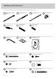
Hardware Identification å Screws are shown actual size. You may receive extra hardware with your unit.
Hardware Usage Guide HOW TO USE A HIDDEN CAM & CAM SCREW OR CAM DOWEL 1. NOTE: Various CAM SCREWS or a CAM DOWEL may be used. Turn the CAM SCREW or gently tap the CAM DOWEL until the shoulder is against the surface of the part. Cam Screws 2. Arrow Cam Dowel Push a HIDDEN CAM into the part. The arrow in the HIDDEN CAM must point toward the hole in the edge of the board. Hidden Cam Hole 3. Insert the CAM SCREW or CAM DOWEL into the HIDDEN CAM. Tighten the HIDDEN CAM.
Step 1 Look for this icon. It means a video assembly tip is available at www.sauder.com/service/tips Find the numbered video or scan the QR code. å Assemble your unit on a carpeted floor or on the empty carton to avoid scratching your unit or the floor. å å Push four HIDDEN CAMS (1) into the ENDS (B and C). Just think. The sooner you do this, the sooner you do something else. Turn four CAM SCREWS (2) into the ENDS (B and C).
Step 2 å Fasten six UNIVERSAL CABINET RAILS* (35AA) to the ENDS (B and C). Use twelve 3/8" FLAT HEAD SCREWS (9) through holes #1 and #3.
Step 3 å å å å Push two HIDDEN CAMS (1) into the UPRIGHT (D). Turn two CAM SCREWS (2) into the UPRIGHT (D). Flip the UPRIGHT (D) over. Turn two CAM SCREWS (2) into the UPRIGHT (D).
Step 4 å Fasten three UNIVERSAL CABINET RAILS* (35AA) to the UPRIGHT (D). Use six 3/8" FLAT HEAD SCREWS (9) through holes #1 and #3. å å å *patent pending glide system å *patent pending glide system Flip the UPRIGHT (D) over. Fasten three UNIVERSAL CABINET RAILS* (35AA) to the UPRIGHT (D). Use six 3/8" FLAT HEAD SCREWS (9) through holes #1 and #3.
Step 5 å å Push two HIDDEN CAMS (1) into one of the BOTTOMS (E). Repeat this step for the remaining BOTTOMS.
Step 6 å Insert four LARGE WOOD DOWELS (3) into the BOTTOMS (E). å Fasten the BOTTOMS (E) to the UPRIGHT (D). Tighten four HIDDEN CAMS. å NOTE: Be sure the WOOD DOWELS in the BOTTOMS insert into the UPRIGHT. Caution Do not stand the unit upright without the BACK fastened. The unit may collapse.
Step 7 å Insert four LARGE WOOD DOWELS (3) into the BOTTOMS (E). å Fasten the ENDS (B and C) to the BOTTOMS (E). Tighten four HIDDEN CAMS. å NOTE: Be sure the WOOD DOWELS in the BOTTOMS insert into the ENDS.
Step 8 å å Turn six CAM SCREWS (2) into the TOP (A). Open the FURNITURE TIPPING RESTRAINT KITS (96) and fasten the SAFETY STRAPS to the TOP (A). Use the provided SHORT SCREWS. 2 A s ole Sur e fac h with Use the SHORT SCREW from the RESTRAINT KIT.
Step 9 å å Insert six LARGE WOOD DOWELS (3) into the TOP (A). å NOTE: Be sure the WOOD DOWELS in the TOP insert into the ENDS and UPRIGHT. Fasten the TOP (A) to the ENDS (B and C) and UPRIGHT (D). Tighten six HIDDEN CAMS. Now might be a good time to refresh your drink.
Step 10 å å Unfold the BACK (F) and lay it over your unit. å Fasten the BACK (F) to the TOP (A), ENDS (B and C), UPRIGHT (D), and BOTTOMS (E). Use twenty-eight 1/2" PAN HEAD SCREWS (8). å NOTE: Be sure the holes line up over the UPRIGHT (D). Caution Push the SAFETY STRAPS through the large holes in the BACK (F). Do not stand the unit upright without the BACK fastened. The unit may collapse. 8 1/2" PAN HEAD SCREW (28 used in this step) Push the SAFETY STRAP through the hole.
Step 11 å Fasten the BRACES (N) to the FEET (M). Tighten six 1/2" HEX HEAD SCREWS (10) using the L-WRENCH (5). å NOTE: You should start each SCREW a few turns before completely tightening any of them.
Step 12 å Fasten the BRACES (N) to the ENDS (B and C) and UPRIGHT (D). Tighten nine 1-3/4" HEX HEAD SCREWS (12) using the L-WRENCH (5). å NOTE: You should start each SCREW a few turns before completely tightening any of them.
Step 13 å Push four HIDDEN CAMS (1) into the DRAWER SIDES (H and P). å Repeat this step for the remaining DRAWER SIDES.
Step 14 1 2 Groove Arrow 1 (6 used) P L J H 4 (24 used) 7 G 1-1/2" FLAT HEAD SCREW (30 used in this step) å å å 3 Insert four SMALL WOOD DOWELS (4) into the DRAWER SIDES (H and P). Fasten the DRAWER SIDES (H and P) to the DRAWER BACK (J). Use four 1-1/2" FLAT HEAD SCREWS (7). NOTE: Be sure the SMALL WOOD DOWELS in the DRAWER SIDES insert into the DRAWER BACK. ed nishce fi n U urfa s H å (30 used) å å Push a HIDDEN CAM (1) into the DRAWER BRACE (L).
Step 15 å Fasten the DRAWER RIGHT (35AC) to the RIGHT DRAWER SIDE (P) and the DRAWER LEFT (35AD) to the LEFT DRAWER SIDE (H). Use four 3/8" FLAT HEAD SCREWS (9) through holes #1 and #2. å å NOTE: The glides are not intended to rotate. å Repeat this step for the remaining drawers. If you're doing this to help a friend, don't leave without a bite. Fasten a PULL (Q) to the DRAWER FRONT (G). Use four 9/16" FLAT HEAD SCREWS (11).
Step 16 å å Carefully stand your unit upright. å NOTE: Be sure the label on the LEFT DRAWER SIDE is in the UPPER drawer. To insert the drawer into your unit, tip the front of the drawer down and drop the glides on the drawer behind the glides on the unit. Lift the front of the drawer up and slide it into the unit. WARNING Children have died from furniture tipover. To reduce the risk of furniture tipover: • ALWAYS install tipover restraint provided. • NEVER put a TV on this product.
Step 17 å å Place your unit in its final location. å 1st- Locate the center of a stud in your wall near your unit and mark it with a pencil. å å 2nd- Drill a 1/8" hole on the mark and into the stud in your wall. å Repeat this step for the remaining SAFETY STRAP. NOTE: The following instructions show your unit being fastened to a wall stud. If you are not fastening your unit to a wall stud, go to the next step now. 3rd- Fasten the unit to the wall.
Step 18 å 1st- With your pencil, strike a mark through the center of the hole in the SAFETY STRAP. å å 2nd- Drill a 3/8" hole on the mark. 3rd- While you squeeze the wings together, gently tap the WALL ANCHOR from the FURNITURE TIPPING RESTRAINT KIT (96) into the hole until it is even with the surface of the wall. å 4th- Turn the LONG SCREW through the hole in the SAFETY STRAP and into the WALL ANCHOR.
Step 19 å å å Peel APPLIQUES from the APPLIQUE CARDS (6) and stick them onto each visible HIDDEN CAM. NOTE: Please read the back pages of the instruction booklet for important safety information. This completes assembly. Clean with a damp cloth. Wipe dry. To cover HIDDEN CAMS 6 (24 used) 35 35 lbs. Page 24 lbs.
Commode Utilisez les instructions d’assemblage en français avec les schémas étape par étape du manuel d’instruction en anglais. Chaque étape en français correspond à la même étape en anglais. Comparer la “Liste de pièces” ci-dessous avec la “PART IDENTIFICATION” du manuel en anglais pour vous familiariser avec les pièces avant l’assemblage. REMARQUE : CE MANUEL D’INSTRUCTIONS CONTIENT D’IMPORTANTES INFORMATIONS RELATIVES À LA SÉCURITÉ. À LIRE ET CONSERVER POUR TOUTE RÉFÉRENCE FUTURE.
Guide d'utilisation de la visserie UTILISATION DE LA EXCENTRIQUE ESCAMOTABLE ET DE LA VIS D'EXCENTRIQUE OU DE LA CHEVILLE D’EXCENTRIQUE 1. REMARQUE : Plusieurs VIS D'EXCENTRIQUE ou une CHEVILLE D’EXCENTRIQUE peut être utilisé. Faire tourner la VIS D'EXCENTRIQUE ou taper doucement la CHEVILLE D'EXCENTRIQUE jusqu'à ce que l'épaulement repose sur la surface de la pièce. 2. Enfoncer un EXCENTRIQUE ESCAMOTABLE dans la partie.
ÉTAPE 8 ÉTAPE 12 Faire tourner six VIS D'EXCENTRIQUE (2) dans le DESSUS (A). Fixer les ENTRETOISES (N) aux EXTRÉMITÉS (B et C) et au MONTANT (D). Serrer neuf VIS TÊTE HEX 44 mm (12) à l’aide de la CLÉ EN L (5). Ouvrir le KIT DE RETENUE ANTI-BASCULEMENT POUR MOBILIER (96) et fixer les SANGLES DE SÉCURITÉ au DESSUS (A). Utiliser les VIS COURTES fournies. ÉTAPE 9 Insérer six GRANDES CHEVILLES EN BOIS (3) dans le DESSUS (A). Fixer le DESSUS (A) aux EXTRÉMITÉS (B et C) et au MONTANT (D).
ÉTAPE 15 ÉTAPE 18 Fixer un TIROIR DROIT (35AC) sur le CÔTÉ DROIT DE TIROIR (P) et un TIROIR GAUCHE (35AD) sur le CÔTÉ GAUCHE DE TIROIR (H). Utiliser quatre VIS TÊTE PLATE 9,5 mm (9) à travers les trous nº 1 et nº 2. 1-Avec un crayon, mettre une marque à travers le centre du trou dans la SANGLE DE SÉCURITÉ. REMARQUE : Les coulisses ne sont pas sensées tourner. Fixer une POIGNÉE (Q) sur le DEVANT DE TIROIR (G). Utiliser quatre VIS TÊTE PLATE 14 mm (11). 2-Percer un trou de 9,5 mm sur la marque.
Cómoda Use estas instrucciones de ensamblaje en español junto con las figuras paso-a-paso provistas en el folleto inglés. Cada paso en español corresponde al mismo paso en inglés. Compare la “Lista de Part” abajo con la “Part Identification” en el folleto en inglés para familiarizarse con Las partes de ensamblaje. NOTA: ESTE FOLLETO DE INSTRUCCIONES CONTIENE INFORMACIÓN IMPORTANTE SOBRE LA SEGURIDAD. POR FAVOR LEA Y GUÁRDELO PARA REFERENCIA EN EL FUTURO.
Guía de uso de herrajes PASO 4 CÓMO UTILIZAR EL EXCÉNTRICO ESCONDIDO Y LA BIELA DE EXCÉNTRICO O PASADOR DE EXCÉNTRICO Fije tres RIELES UNIVERSALES DE GABINETE* (35AA) al PARAL (D). Utilice seis TORNILLOS DE CABEZA PERDIDA de 9,5 mm (9) a través de los agujeros No. 1 y No. 3. 1.. NOTA: Varias BIELAS DE EXCÉNTRICO o un PASADOR DE EXCÉNTRICO pueden ser utilizados. Gire una BIELA DE EXCÉNTRICO o ligeramente golpee el PASADOR DE EXCÉNTRICO hasta que el resalto repose contra de la parte. 2..
PASO 8 PASO 12 Atornille seis BIELAS DE EXCÉNTRICO (2) dentro del PANEL SUPERIOR (A). Fije las RIOSTRAS (N) a los EXTREMOS (B y C) y al PARAL (D). Apriete nueve TORNILLOS DE CABEZA HEXAGONAL de 44 mm (12) utilizando la LLAVE EN L (5). Abrir el KIT DE CONTROL ANTI-INCLINACIÓN PARA MOBILIARIO (96) y fijar las CORREAS DE SEGURIDAD al PANEL SUPERIOR (A). Utilice los TORNILLOS CORTOS provistos. NOTA: Debe apretar cada TORNILLO unas vueltas antes de apretar cualquier tornillo firmemente.
PASO 15 PASO 18 Fije el CAJÓN DERECHO (35AC) al LADO DERECHO DE CAJÓN (P) y un CAJÓN IZQUIERDO (35AD) al LADO IZQUIERDO DE CAJÓN (H). Utilice cuatro TORNILLOS DE CABEZA PERDIDA de 9,5 mm (9) a través de los agujeros No. 1 y No. 2. 1-Con su lápiz, ponga una marca a través del centro del agujero en la CORREA DE SEGURIDAD. NOTA: Los corrimientos no están concebidos para rotar. Fije un TIRADOR (Q) a la CARA DE CAJÓN (G). Utilice cuatro TORNILLOS DE CABEZA PERDIDA de 14 mm (11).
WARNING Please use your furniture correctly and safely. Improper use can cause safety hazards, or damage to your furniture or household items. Carefully read the following safety information. Death or serious injury may occur when children climb on furniture. A remote control, toys or other items placed on the furniture may encourage a child to climb on the furniture which could cause it to tip-over and result in serious injury or death. NEVER allow children to climb on furniture.
ADVERTENCIA Por favor use el mobiliario correcta y seguramente. El mal uso puede causar riesgos de seguridad o daño a las unidades o artículos domésticos. Lea cuidadosamente la siguiente información de seguridad. Pueden suceder lesiones graves o la muerte cuando los niños se suben en los muebles. Un control remoto, juguetes u otros artículos colocados en los muebles pueden alentar a un niño a subirse en el mueble, lo cual podría causar que se derribe y resultaría en lesiones graves o la muerte.
5-YEAR LIMITED WARRANTY 1. Sauder Woodworking Co. (Sauder®) provides limited warranty coverage to the original purchaser of this product for a period of five years from the date of purchase against defects in materials or workmanship of Sauder furniture components. As used in this Warranty, “defect” means imperfections in components which substantially impair the utility of the product. This Warranty gives you specific legal rights, and you may also have other rights which vary from state to state. 2.