
Installation Guide User guide

1 2
3
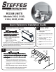
Quick Reference Installation Guide
ROOM UNITS
Models 2102, 2103,
2104, 2105, 2106
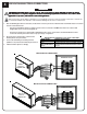
PLACEMENT AND CLEARANCES
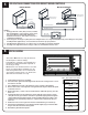
INITIAL SETUP
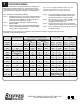
SECURING THE HEATER
“Manufactured in North America”
Bolt
Carriage
23 1/2"
F
l
o
o
r
W
a
l
l
S
u
p
p
o
r
t
B
r
a
c
k
e
t
Lag Bolts
Attached to Studs
Clip
Wall Support
Risk ofRisk of
Risk ofRisk of
Risk of
f f
f f
f
irir
irir
ir
ee
ee
e
..
..
.
Can cause injur Can cause injur
Can cause injur Can cause injur
Can cause injur
y ory or
y ory or
y or
death. Violation of the clearancedeath. Violation of the clearance
death. Violation of the clearancedeath. Violation of the clearance
death. Violation of the clearance
requirements can cause improperrequirements can cause improper
requirements can cause improperrequirements can cause improper
requirements can cause improper
operation of the equipment.operation of the equipment.
operation of the equipment.operation of the equipment.
operation of the equipment.
Maintain the placement andMaintain the placement and
Maintain the placement andMaintain the placement and
Maintain the placement and
clearance requirements specified.clearance requirements specified.
clearance requirements specified.clearance requirements specified.
clearance requirements specified.
NOTE
A clearance of 12" is recommended on the right side of heater. If there is less than
a 12" clearance, a remote room temperature sensor is recommended to ensure
accurate room temperature sensing. The 12" clearance also allows space for
hinging the right side panel open for servicing.
WARNINGWARNING
WARNINGWARNING
WARNING
A Top = 4 inches
B Front and Grill = 15 inches
C Sides = 2 inches (See Note)
D Back = 1-1/2 inches
1. Unbox heater and lift it off the
shipping pallet.
2. Place heater in the desired location.
3. Check for proper clearances on all
sides.
4. Remove screws at lower edge of
painted front panel.
5. Pull the lower edge of the panel
forward and unhook it from the top
panel.
6. Carefully place painted front panel
aside.
WARNINGWARNING
WARNINGWARNING
WARNING
Risk ofRisk of
Risk ofRisk of
Risk of
f f
f f
f
irir
irir
ir
ee
ee
e
..
..
.
Can cause injur Can cause injur
Can cause injur Can cause injur
Can cause injur
y or deay or dea
y or deay or dea
y or dea
th.th.
th.th.
th.
F F
F F
F
ailurailur
ailurailur
ailur
e toe to
e toe to
e to
secursecur
secursecur
secur
e the heae the hea
e the heae the hea
e the hea
ter can cause the heater can cause the hea
ter can cause the heater can cause the hea
ter can cause the hea
ter to fter to f
ter to fter to f
ter to f
all oall o
all oall o
all o
vv
vv
v
erer
erer
er
..
..
.
PrPr
PrPr
Pr
operoper
operoper
oper
ll
ll
l
y secury secur
y secury secur
y secur
e the heae the hea
e the heae the hea
e the hea
ter bter b
ter bter b
ter b
y using the wy using the w
y using the wy using the w
y using the w
all supporall suppor
all supporall suppor
all suppor
tt
tt
t
bracket to mount it to the wall or by installing thebracket to mount it to the wall or by installing the
bracket to mount it to the wall or by installing thebracket to mount it to the wall or by installing the
bracket to mount it to the wall or by installing the
security base.security base.
security base.security base.
security base.
1. Remove the mounting hardware package from its
shipping position inside the electrical compartment.
2. Place the top of the wall support bracket 23-1/2" from
the floor and secure it to the wall with the lag bolts
provided.
3. Attach the wall support clips to the back of the heater.
4. Set the carriage bolts aside as they will be used later
to attach the heater to the wall support bracket.
D
B
C
A
C