V3 TROUBLESHOOTING GUIDE FOR HEAT PUMP BOOSTERS MODELS: HPB11, HPB15, & HPB22
PREFACE This guide contains instructions for troubleshooting the Steffes Corporation room heating units: Models HPB 11, HPB 15, and HPB 22. In compiling this guide, Steffes Corporation has used its best judgment based upon information available but disclaims any responsibility or liability for any errors or miscalculations, contained herein, or any revisions, hereof, or which result, whole or in part, from the use of this guide, or any revision hereof.
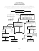
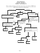
Heat Pump Booster Function: Core Charging Problem: Unit will not charge (Unit has no core charge) or Control Board lights are off. Before starting any of the procedures below, check voltage on load side of all HPB circuit breakers and check low voltage fuses on charge control circuit board. Place unit in off-peak mode. Check utility switch and HPB off-peak light on charge control circuit board for proper operation.
Heat Pump Booster Function: Core Charging Problem: Unit undercharges Before starting any of the procedures below, check voltage on load side of all HPB circuit breakers. Check for 24 VAC between each of the 3-amp low voltage fuses and the "C" position (thermostat connection) on the charge control circuit board's terminal block. Unit undercharges on cold days thermostat Check charge control thermostat knob for proper position. Lessthan than Less Maxusage usage Max Check daily kWh usage.
Heat Pump Booster Function: Core Charging Problem: Unit overcharges on warm days Before starting any of the procedure below, check voltage on load side of all HPB circuit breaker and check low voltage fuses on charge control circuit board.
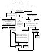
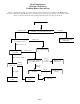
Heat Pump Booster Function: Air Delivery Problem: Cool discharge air Before starting any of the procedure below, check voltage on load side of all HPB circuit breakers. Check for 24 VAC between each of the low voltage fuses the "C" position on the charge control circuit board's terminal block.. Blower delivers cool Cold All Stages discharge air. Blower deliversUncertain cool Cold Stage One Cold All Stages discharge air.
Heat Pump Booster Function: Air Delivery Problem: Blower does not run Before starting any of the procedure below, check voltage on load side of all HPB circuit breakers. Check for 24 VAC between each of the low voltage fuses and the "C" position on the charge controls circuit board's terminal block. Put heater into peak mode. Initiate a peak mode. Initiate a peak mode. Check for 24 VAC across "R" and "C" terminals on booster interface board (21).
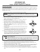
DISCHARGE AIR Check-Out Procedure Models: HPB11B, HPB15B and HPB22B CHECK OUT PROCEDURE: The failure of the melt link is often the result of another problem that exists within the booster. Typically, the failure is a direct result of the inability of the booster to regulate its output temperature. If the primary problem is not rectified, melt link failure could occur again. Thus, after the failed melt link has been replaced, the booster MUST be tested to ensure that failure will not reoccur. 1.
Discharge Air Check Out Procedure Continued… 15. Energize the control circuit and check the #4 yellow LED light on the interface board. It should remain on (indicates the damper is satisfied), and there should be 24 VAC between the CW terminal and the COM terminal on the damper motor. 16. If any of the voltage tests performed in this check-out procedure do not yield the correct results, check connections from the booster’s interface board to the air discharge sensor. 17.
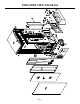
EXPLODED VIEW DIAGRAM Page 8
HPB PARTS LIST NOTE: When ordering replacement parts, please include unit model number and serial number. DWG. REF. NO. 1. 2. 3. 4. 5. 6. 7. 8. 9. 10. 11. 12. 13. 14. 15. 16. 17. 18. 19. 20. 21. 22. 23. 24. 25. 26. 27. 28. 29. 30. 31. 32. 33. 34. 35. 36. 37. 38.
DWG. REF. NO. 39. 40. 41. 42. 43. 44. 45. 46. 47. 48. 49. 50. 51. 52. 53. 54. 55. 56. 57. 58. 59. 60. 61. 62.