Plug-in Reference
Cristina Bachmann, Heiko Bischoff, Marion Bröer, Sabine Pfeifer, Heike Schilling The information in this document is subject to change without notice and does not represent a commitment on the part of Steinberg Media Technologies GmbH. The software described by this document is subject to a License Agreement and may not be copied to other media except as specifically allowed in the License Agreement.
Table of Contents
5 The included effect plug-ins 74 The included VST instruments 6 6 9 15 23 25 30 37 39 46 47 48 Introduction Delay plug-ins Distortion plug-ins Dynamics plug-ins EQ plug-ins Filter plug-ins Modulation plug-ins Pitch Shift plug-ins Reverb plug-ins Spatial + Panner plug-ins Surround plug-ins (Cubase only) Tools plug-ins 75 75 Introduction Embracer – Surround Pad Synthesizer (Cubase only) Groove Agent ONE HALion Sonic SE LoopMash Monologue – Monophonic Analog Modeling Synthesizer (Cubase only) Mystic Pr
1 The included effect plug-ins
Introduction This chapter contains descriptions of the included plug-in effects and their parameters. In Cubase, the plug-in effects are arranged in a number of different categories. This chapter is arranged in the same fashion, with the plug-ins listed in separate sections for each effect category.
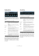
MonoDelay Parameter Description Range Lo/Hi These knobs specify the range (in Hz) of the filter frequency modulation. Both positive (e. g. Lo set to 50 and Hi set to 10000) and negative (e. g. Lo set to 5000 and Hi set to 500) ranges can be set. If tempo sync is off and the Speed is set to zero, these parameters are inactive and the filter frequency is controlled by the Freq parameter instead.
PingPongDelay StereoDelay StereoDelay has two independent delay lines which either use tempo-based or freely specified delay time settings. The following parameters are available: This is a stereo delay effect that alternates each delay repeat between the left and right channels. The effect can either be tempo-based or use freely specified delay time settings.
Distortion plug-ins BitCrusher This section contains descriptions of the plug-ins in the “Distortion” category. AmpSimulator AmpSimulator is a distortion effect, emulating the sound of various types of guitar amp and speaker cabinet combinations. A wide selection of amp and cabinet models is available. The following parameters are available: If you are into lo-fi sound, BitCrusher is the effect for you.
DaTube Parameter Description Spatial Changes the distortion characteristics of the left and right channel, thus creating a stereo effect. Output Raises or lowers the signal going out of the effect. Grungelizer This effect emulates the characteristic warm, lush sound of a tube amplifier. The following parameters are available: Parameter Description Drive Regulates the pre-gain of the “amplifier”. Use high values if you want an overdriven sound just on the verge of distortion.
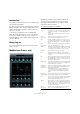
SoftClipper (Cubase only) VST Amp Rack The VST Amp Rack is a powerful guitar amp simulator. It offers a choice of amplifiers and speaker cabinets that can be combined with stomp box effects. The plug-in processes the mono sum of the channel and outputs a mono or stereo signal, depending on the track configuration. This effect adds soft overdrive, with independent control over the second and third harmonic. The following parameters are available: Parameter Description Input Regulates the pre-gain.
Effect Description Effect Option Description Compressor Intensity Changes the intensity of the compressor effect. Delay Chorus Rate Allows you to set the sweep rate. This parameter can be synchronized to the project tempo, see “Sync mode” on page 13. Tape Ducking Delay Tape Ducking Delay creates a delay effect known from tape machines with a ducking parameter. The Delay parameter sets the delay time in milliseconds.
Sync mode The following amp models are available: For some controls, the sync mode can be activated to synchronize the corresponding parameter with the tempo of the host application. These plug-in parameters are then used to specify the base note value for tempo syncing (1/1 to 1/32, straight, triplet, or dotted). Using effects • Plexi – Classic British rock tone; extremely transparent sound, very responsive. • Plexi Lead – British rock tone of the 70’s and 80’s.
You can choose between two microphone types: a largediaphragm condenser microphone and a dynamic microphone. Crossfading between the characteristics of the two microphones is also possible. View settings Placing the microphone In the default view, you can use the top buttons to open the corresponding page in the Display section above the amp controls. In the compact view the page display is hidden from view. You can still change the amp settings and switch amps or cabinets using the mouse wheel.
Previewing effect settings The following parameters are available: In both views, you can show a preview of the pre- and post-effects that you selected on the corresponding pages: Parameter Description Threshold (-60 to 0 dB) Determines the level where Compressor “kicks in”. Signal levels above the set threshold are affected, but signal levels below are not processed. Ratio (1:1 to 8:1) Sets the amount of gain reduction applied to signals over the set threshold.
DeEsser (Cubase only) Positioning the DeEsser in the signal chain When recording a voice, the de-esser’s position in the signal chain is usually located after the microphone preamp and before a compressor/limiter. This keeps the compressor/limiter from unnecessarily limiting the overall signal dynamics. EnvelopeShaper A de-esser is used to reduce excessive sibilance, primarily for vocal recordings.
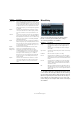
Expander (Cubase only) Expander reduces the output level in relation to the input level for signals below the set threshold. This is useful when you want to enhance the dynamic range or reduce the noise in quiet passages. You can either use the knobs or drag the breakpoints in the graphical display to change the Threshold and the Ratio parameter values.
Limiter Parameter Description Filter buttons (LP, BP, and HP) When the Side-Chain button (see below) is activated, you can use these buttons to set the filter type to either low-pass, band-pass, or high-pass. Side-Chain button This button (below the Center knob) activates the sidechain filter. The input signal can then be shaped according to set filter parameters. Internal side-chaining can be useful for tailoring how the Gate operates.
Maximizer MIDI Gate Maximizer is used to raise the loudness of audio material without the risk of clipping. Optionally, there is a soft clip function that removes short peaks in the input signal and introduces a warm tube-like distortion to the signal. Gating, in its fundamental form, silences audio signals below a set threshold level. When a signal rises above the set level, the gate opens to let the signal through while signals below the set level are cut off.
5. Make sure the MIDI track is selected, and start playback. MultibandCompressor (Cubase only) 6. Play a few notes on your MIDI keyboard. As you can hear, the audio track material is affected by what you play on your MIDI keyboard. The following MIDI Gate parameters are available: Parameter Description Attack Determines how long it takes for the gate to open after receiving a signal that triggers it.
VintageCompressor (Cubase only) Bypassing frequency bands Each frequency band can be bypassed using the B button in each compressor section. Soloing frequency bands A frequency band can be soloed using the S button in each compressor section. Only one band can be soloed at a time. Using the Compressor section By moving breakpoints or using the corresponding knobs, you can specify the Threshold and Ratio.
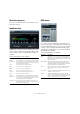
VSTDynamics Gate Compressor Limiter Module Configuration VSTDynamics is an advanced dynamics processor. It combines three separate processors: Gate, Compressor and Limiter, covering a variety of dynamic processing functions. The window is divided into three sections, containing controls and meters for each processor. Activating the individual processors You activate the individual processors using the buttons at the bottom of the plug-in panel.
EQ plug-ins The Limiter section The limiter is designed to ensure that the output level never exceeds a set threshold, to avoid clipping in following devices. Conventional limiters usually require very accurate setting up of the attack and release parameters to prevent the output level from going beyond the set threshold level. The limiter adjusts and optimizes these parameters automatically according to the audio material. You can also adjust the Release parameter manually.
Apart from the frequency bands, the following parameters are available: Parameter Description Output Controls the overall gain of the equalizer. Flatten button Resets all the frequency bands to 0 dB. Range Allows you to relatively adjust how much a set curve cuts or boosts the signal. If the Range parameter is turned fully clockwise, the range is +/-12 dB. Invert button Inverts the current response curve.
The following parameters are available: Parameter Description Parameter Description Band 1 Gain (-20 to +24 dB) Sets the amount of cut/boost for the low band. Band 4 Filter mode Band 1 Inv button Inverts the gain value of the filter. Use this button to filter out unwanted noise. While looking for the frequency to omit, it sometimes helps to boost it in the first place (set the filter to positive gain). After you have found it, you can use the Inv button to cancel it out.
StepFilter Selecting new patterns • Created patterns are saved with the project, and up to 8 different cutoff and resonance patterns can be saved internally. Both the cutoff and resonance settings are saved together in the 8 pattern slots. • Use the Pattern Selector below the Resonance grid to select a new pattern. New patterns are all set to the same step value by default.
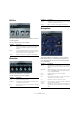
ToneBooster Tonic (Cubase only) Tonic is a versatile and powerful analog modeling filter plug-in based on the filter design of the Monologue monophonic synthesizer. Its variable characteristics plus the powerful modulation functions make it an excellent choice for all current music styles. Designed to be more a creative tool rather than a tool to fix audio problems, it can add color and punch to your tracks while being light on CPU usage.
Filter X/Y Pad In the Filter section at the center of the plug-in panel, the following parameters are available: In the X/Y Pad at the bottom left of the plug-in panel, the following parameters are available: Parameter Description Parameter Description Mode pop-up menu Sets the filter type. Available filter types are: 24 dB lowpass, 18 dB low-pass, 12 dB low-pass, 6 dB low-pass, 12 dB band-pass, and 12 dB high-pass. X Par pop-up menu Sets the parameter to be modulated on the x-axis of the XY Pad.
WahWah Mastering – UV22HR WahWah is a variable slope band-pass filter that can be auto-controlled by a side-chain signal or via MIDI modeling the well-known analog pedal effect (see below). You can independently specify the frequency, width and the gain for the Lo and Hi Pedal positions. The crossover point between the Lo and Hi Pedal positions lies at 50. The UV22HR is a dithering plug-in, based on an advanced algorithm developed by Apogee.
Modulation plug-ins Chopper This section contains descriptions of the plug-ins in the “Modulation” category. AutoPan This is a simple auto-pan effect. It can use different waveforms to modulate the left-right stereo position (pan), either using tempo sync or manual modulation speed settings. The following parameters are available: Parameter Description Rate If tempo sync is on, this is where you specify the base note value for tempo-syncing the effect (1/1 to 1/32, straight, triplet, or dotted).
Ö The modulation can also be controlled from another signal source via the side-chain input. When the sidechain signal exceeds the threshold, the modulation is controlled by the side-chain signal’s envelope. For a description of how to set up side-chain routing, see the chapter “Audio effects” in the Operation Manual. Chorus Cloner (Cubase only) This is a single-stage chorus effect.
Parameter Description Parameter Description Static Detune button Use this button to activate/deactivate the Static Detune function. If activated, the set detune amount is static, and the Humanize knob is grayed out. Mix Delay Governs the overall depth of the delay for all voices. If set to zero, no delay takes place regardless of the Delay slider settings. Sets the level balance between the dry and the wet signal.
Metalizer Phaser Metalizer feeds the audio signal through a variable frequency filter, with tempo sync or time modulation and feedback control. Phaser produces the well-known “swooshing” phasing effect with additional stereo enhancement. The following parameters are available: The following parameters are available: Parameter Description Parameter Description Rate Feedback The higher the value, the more “metallic” the sound. Sharpness Governs the character of the filter effect.
Ö The modulation can also be controlled from another signal source via the side-chain input. When the sidechain signal exceeds the threshold, the modulation is controlled by the side-chain signal’s envelope. For a description of how to set up side-chain routing, see the chapter “Audio effects” in the Operation Manual. RingModulator RingModulator can produce complex, bell-like enharmonic sounds. Ring modulators work by multiplying two audio signals.
The following parameters are available: Directing MIDI to the Rotary Parameter Description Speed selector (Stop/ Slow/Fast) Allows you to control the speed of the Rotary in three steps. For realtime MIDI control of the Speed parameter, MIDI must be directed to the Rotary. Speed Change Mode Allows you to select whether the Slow/Fast setting is a switch (left) or a variable control (right).
Parameter Description Parameter Description Delay Affects the frequency range of the modulation sweep by adjusting the initial delay time. Sync button The button above the Speed knob is used to switch tempo sync on (button lights up) or off. Filter Lo/Hi Allow you to roll off low and high frequencies of the effect signal. On button Turns modulation of the pitch parameter on or off. Mono button Governs whether the output is stereo or mono.
Vibrato Pitch Shift plug-ins This section contains descriptions of the plug-ins in the “Pitch Shift” category. Octaver The Vibrato plug-in produces pitch modulation. The following parameters are available: Parameter Description Rate If tempo sync is on, this is where you specify the base note value for tempo-syncing the effect (1/1 to 1/32, straight, triplet, or dotted). If tempo sync is off, the modulation speed can be set freely with the Rate knob.
Pitch Correct Pitch Correct automatically detects, adjusts and fixes slight pitch and intonation inconsistencies in monophonic vocal and instrumental performances in realtime. The advanced algorithms of this plug-in preserve the formants of the original sound thus allowing for natural sounding pitch correction without the typical “Mickey Mouse” effect. Furthermore, you can use Pitch Correct creatively.
Reverb plug-ins This section contains descriptions of the plug-ins in the “Reverb” category. output settings” on page 42). The program matrix allows you to load programs and to view the name of the current program, i. e. the impulse response (see “Working with custom impulse responses” on page 42). REVerence (Cubase only) The following parameters are available: REVerence is a convolution tool that allows you to apply room characteristics (reverb) to the audio.
Programs vs. presets Setting up programs You can save your REVerence settings as VST plug-in presets or programs. The differences between the two and the advantages are described in the following. Proceed as follows: Both presets and programs use the file extension .vstpreset and appear in the same category in the MediaBay (Plug-In Presets), but they are represented by different icons: A blinking white frame indicates that this program slot is selected.
Parameter Description Making EQ settings Level A level control for the impulse response. This governs the volume of the reverb. In the Equalizer section you can tune the sound of the reverb. ER Tail Split Sets a split point between the early reflections and the tail, allowing you to determine where the reverb tail begins. A value of 60 means that the early reflections will be heard for 60 ms. ER Tail Mix Allows you to set up the relation of early reflections and tail.
Loading pictures The following parameters are available: In the Pictures section you can load graphics files to illustrate the setting, i. e. the recording location or microphone arrangement of the loaded impulse response. Up to five pictures can be loaded. Parameter Description Output activity meter Indicates the overall level of the impulse response and its settings. Output slider Allows you to adjust the overall output level. Out (-24 to +12) Raises or lowers the signal output of the plug-in.
3. Make the appropriate settings and add a picture, if available. Pictures residing in the same folder as the impulse response file or in the parent folder are automatically found and displayed. 4. Click the Store button to save the impulse response and its settings as a program. That way you can recall the setup at any time. The program slot turns blue, indicating that a program is loaded. Ö When saving a program, the impulse response file itself is only referenced.
User content is a different matter, though. If you have transferred your audio files to an external drive or a different hard disk location on the other computer, REVerence cannot access the impulse responses any more since the old file paths have become invalid. The following parameters are available: To access your impulse responses again, proceed as follows: Input – Hi Freq Determines the frequency at which the high-shelving filter takes effect.
RoomWorks SE Parameter Description Envelope – Attack The envelope settings in RoomWorks control how the reverb will follow the dynamics of the input signal in a fashion similar to a noise gate or downward expander. Attack determines how long it takes for the reverb to reach full volume after a signal peak (in milliseconds). This is similar to a pre-delay but the reverb is ramping up instead of starting all at once.
Spatial + Panner plug-ins StereoEnhancer This section contains descriptions of the plug-ins in the “Spatial + Panner” category. MonoToStereo This plug-in will expand the stereo width of (stereo) audio material. It cannot be used with mono files. The following parameters are available: Parameter Description This effect will turn a mono signal into a “pseudo-stereo” signal. The plug-in must be inserted on a stereo track playing a mono file. Width Controls the width or depth of the stereo enhancement.
Surround plug-ins (Cubase only) MixerDelay This section describes the plug-ins in the “Surround” category. Mix6To2 MixerDelay allows you to adjust and manipulate each individual channel in a surround track, group or bus. • Above the individual channel controls you will find global buttons for turning off Mute, Solo and Invert Phase switches for all channels. For each channel the following controls are available: Mix6To2 lets you quickly mix down your surround mix format to stereo.
distant speakers. Note that MixerDelay has a wide range (up to 1000 ms) and fine adjustments are best made by numerically entering the delay time in centimeters for speaker alignment. ! The MixerDelay is not a mixer – the number of outputs is the same as the number of inputs. If you need to mix down a surround signal to stereo, use the Mix6to2, Mix8to2 or MixConvert plug-ins. Tools plug-ins This section describes the plug-ins in the “Tools” category.
• By adjusting the Frequency knob, you can divide the frequency spectrum into 8, 15, or 31 bands, or you set it to “Spectrum”, which gives you a high-resolution view. When MultiScope is used with a surround channel in Scope mode, the pop-up menu to the right of the Scope button determines the result: • Use the Mode A and Mode B buttons to switch between different view modes.
Parameter Description Offset timecode display This display is only available if “Link to Transport” is activated. It allows you to set an offset with regard to the timecode used by Cubase. The offset affects the generated SMPTE signal, the current cursor position in Cubase remains unaffected. For example, use this when playing back video using an external device, where the video starts at a different timecode position than in Cubase.
Parameter Description Frequency section Allows you to set the frequency of the generated signal. You can select one of the preset values (100, 440, 1000, or 10000 Hz), or use the slider to set a value between 1 Hz and 20000 Hz. Gain section Allows you to set the amplitude of the signal. The higher the value (up to 0 dB), the stronger the signal. You can select one of the preset values (e. g. -20 dB), or use the slider to set a value between -81 and 0 dB. Tuner This is a guitar tuner.
2 MIDI effects
Introduction 4. Use the Length setting to set the length of the arpeggio notes. This chapter describes the included MIDI realtime effects and their parameters. This allows you to create staccato arpeggios (Length value smaller than the Step Size setting) or arpeggio notes that overlap each other (Length value greater than Step Size). How to apply and handle MIDI effects is described in the chapter “MIDI realtime parameters and effects” in the Operation Manual. 5. Set the Key Range parameter to 12.
Setting Description Classic mode Play Order slots If the User play order is selected, you can use these “slots” to specify a custom playback order for the arpeggio notes: Each of the 12 slots corresponds to a position in the arpeggio pattern. For each slot, you specify which note should be played on that position by selecting a number. The numbers correspond to the keys you play, counted from the lowest pressed key.
Now, the notes in the dropped MIDI part will be sorted internally, either according to their pitch (“MIDI Seq. sort by pitch” checkbox activated) or according to their play order in the part. This results in a list of numbers. For example, if the notes in the MIDI part are C E G A E C and they are sorted according to pitch, the list of numbers will read 1 2 3 4 2 1. Here, there are 4 different notes/numbers and 6 trigger positions.
Density Lane Name fields Step display Jump mode Swing and Offset controls This determines the density of the controller curves sent out. The value can be set to “small”, “medium”, or “large”, or to rhythmically exact note values (by choosing from the pop-up menu). The higher the note value, the smoother the controller curve. For example, if you set this to “1/16”, a new controller event will be sent out at every 1/16 note position.
Selecting drum sounds To specify a drum sound, click in the drum name field for a lane and select the desired drum sound from the pop-up menu. The available drum sounds depend on the selected drum map. If no drum map is selected for the track, the GM (General MIDI) drum names are used. • To find the right sound, you can audition the selected drum sound by clicking the Preview Instrument button (the speaker icon).
• You can mute or solo a lane by clicking the respective buttons to the left of the step display. ! The lane operations always affect all patterns in the Beat Designer instance, not only the one you edit. • You can set up key commands for the Insert options and the Fill Loop command in the Key Commands dialog. How to set up and use key commands is described in the chapter “Key Commands” in the Operation Manual.
Adding flams Offsetting lanes The Flam parameter lets you add flams (short secondary drum hits just before or after the actual main drum beat). To the right of the step display, you can find the Offset sliders for the lanes. These allow you to offset all drum steps on this lane. Drag a slider to the left to make the drum steps start a little earlier and to the right to let them start later. You can add up to three flams for each pattern step: 1.
Using the drum patterns in your project You can use the drum patterns created with the Beat Designer in two ways: either by converting them to MIDI parts on a MIDI or instrument track or by triggering the different patterns using MIDI notes. Converting patterns into MIDI parts You can convert the drum patterns created in the Beat Designer into a MIDI part by dragging them into the Project window. Proceed as follows: 1. Set up one or more patterns of the same subbank. 2.
Now, you can trigger the patterns in the following way: Operating modes 1. Play back the project and press a key on your MIDI keyboard to trigger the next pattern. In the lower left section of the Chorder window, you can choose an option from the Chords pop-up menu to decide which keys in the keyboard display will be used to record your chords. The pattern will start at the next bar line. 2. Create a MIDI part and enter notes at the positions in the project where you want to switch patterns.
Entering chords To enter chords you need to switch to Learn mode. In this mode a transparent red bar indicates which element is ready for “learning” a note or chord. When you choose the trigger note for a chord, for example, the keyboard display is shown in red. • If more than one layer is shown, the Chorder will jump automatically to the next layer where you can record another chord.
The layer modes work as follows: Playstyle Trigger mode Description From the Playstyle pop-up menu at the bottom of the pane you can choose one of seven different styles that determine in which order the individual notes of the chords are played back. Velocity Interval Single Mode The full velocity range (1–127) is divided into “zones”, according to the number of layers you specified.
Parameter Description Poly Mode – Chord Gate Gain This adds or subtracts a fixed value from the velocities. Since the maximum range for velocity values is 0–127, you may need to use the Gain setting to compensate, keeping the resulting velocities within the range. Typically, you would use negative Gain settings when expanding and positive Gain settings when compressing. When Chord Gate is activated, only notes in recognized chords are let through.
Micro Tuner Application examples Poly Mode In Poly mode, you could use the Context Gate to accompany yourself during a live guitar performance using a VST instrument. To do this, you might use a guitar to MIDI converter: You could then program the Context Gate, for example, to allow only those notes to pass the gate that are part of a four-note chord. During your performance you would then play a four-note chord every time that you want to trigger the VST instrument.
etc.). By selecting the correct MIDI controller types, you can use the plug-in as a control panel for adjusting the sound of the instrument from within Cubase, at any time. • To select a controller type, use the pop-up menus on the right. For example, setting this to -2 will cause the first echo note to have a pitch two semitones lower than the original note, the second echo note two semitones lower than the first echo note, and so on.
MIDI Modifiers Length This sets the length of the echoed notes. This can either be identical with the length of the original notes (parameter set to its lowest value) or the length you specify manually. You can either set this to “rhythmically exact” values (displayed as note values – see the table below) or activate the PPQ button and choose a PPQ value. Ö The length can also be affected by the Length Decay parameter. This plug-in is essentially a duplicate of the MIDI Modifiers section in the Inspector.
Note to CC Inputs section In this section you can choose whether to monitor Live Events or Playback Events. Show section Here, you can activate/deactivate the different types of MIDI events, e. g. notes or program change events. If you choose the Controller option you can also define which type of controller to monitor. Data table In the table in the lower section of the window, you will see detailed information about the monitored MIDI events.
While the Quantize function on the Edit menu applies the timing change to the actual notes on a track, the Quantizer effect allows you to apply quantizing “on the fly”, changing the timing of the notes in real time. This makes it easier to try out different settings when creating grooves and rhythms. Note however, that the main Quantize function contains settings and features that are not available in the Quantizer.
• The display spans one octave (as indicated by the pitch list to the left). You can scroll the displayed octave up or down by clicking in the pitch list and dragging up or down. This way you can insert notes at any pitch. Note that each step can contain one note only – the StepDesigner is monophonic. Adding controller curves The Controller pop-up menu has two more items: two controller types. • You can select which two controller types (filter cutoff, resonance, volume, etc.
Track Control Automating pattern changes You can create up to 200 different patterns in each StepDesigner – just select a new pattern and add notes and controllers as described above. Typically, you want the pattern selection to change during the project. You can accomplish this by automating the Pattern selector, either in real time by activating the Write automation and switching patterns during playback or by drawing in the automation track for the StepDesigner’s MIDI track.
About the Reset and Off buttons XG 1 Regardless of the selected mode, you will find two buttons labeled “Off” and “Reset” at the top of the control panel: The following controls are available when the XG 1 mode is selected: Control Description • Clicking the Off button will set all controls to their lowest value, without sending out any MIDI messages. Send 1 Send level for the reverb effect. Send 2 Send level for the chorus effect.
Transformer The Transformer is a realtime version of the Logical Editor. With this you can perform very powerful MIDI processing on the fly, without affecting the actual MIDI events on the track. The Logical Editor is described in the corresponding chapter in the Operation Manual. As the parameters and functions are almost identical, the descriptions for the Logical Editor also apply to the Transformer. Where there are differences between the two, this is clearly stated.
3 The included VST instruments
Introduction • “Eye” controller for simultaneous tone and width control. • Full MIDI control implementation. This chapter contains descriptions of the included VST instruments and their parameters. Osc 1 and 2 Ö Most of the included instruments are compatible with VST3, this is indicated by an icon in front of the name (for further information, see the section “About VST 3” in the chapter “Audio effects” in the Operation Manual).
Master Parameter Description Release Controls the overall release time of the volume envelope. Higher values result in longer release times. Mode Sets the output mode of Embracer. You can choose between “Stereo” and “Surround”. In Stereo Mode, Embracer has one stereo output in the VST Mixer. In Surround Mode, Embracer has either a quadraphonic 4-channel output or two independent stereo outputs in the Mixer. See below for more details on using Embracer in a surround mixer setup.
Groove Agent ONE • You can assign up to eight samples to a pad. See “Drag & drop of audio material” on page 78. • If one or more samples have been assigned to a pad, the name of the first of these samples is displayed at the bottom of the pad. To change the name, right-click it, enter a new name and press [Enter]. This allows you, e. g., to indicate that more than one sample is mapped to this pad.
Resetting pads You can find a Reset button in the Global section in the top right corner of the Groove Agent ONE panel. It allows you to clear all pad assignments of the current instance of Groove Agent ONE. As a safety precaution, the Reset button is locked by default. Clicking the Reset button when it is locked has no effect. To unlock the Reset button, hold down the [Shift] key while clicking. The button color changes to red. When you click Reset now, all pad assignments are reset.
5. Drag this MIDI file from the MIDI Export pad onto the Cubase Project window. Dropping the file onto the Project window creates a new MIDI track. You can also drop the MIDI file to an existing MIDI or instrument track. 6. Play back the MIDI file. The unedited MIDI file plays the same groove as the original audio loop. By editing the MIDI file you can change the original groove.
pads used by this instance of Groove Agent ONE. The Size parameter indicates the amount of RAM occupied by the currently loaded samples. The Polyphony counter shows the number of pads currently playing. Parameter Description Sample This is the name of the sample file. Velocity Here you can specify a velocity range for the current layer. • Click on a pad for sound editing. Coarse Here you can tune the sample by up to ±12 semitones. It turns light green and the display shows its sample parameters.
Parameter Description Master volume Mute Gr. With this control you can assign a pad to one of eight mute groups. Pads within a mute group never play back simultaneously. New notes cancel previous notes. Tr. Mode The sample of the currently selected pad is played either from start to finish (One Shot) or only for as long as you hold the mouse button/key (Key Hold). Key Hold can also be determined by the length of the corresponding MIDI note on your track.
LoopMash Getting started To give you a first impression of what you can do with LoopMash, we have created a tutorial preset. Proceed as follows: 1. In Cubase, create an instrument track with LoopMash as the associated VST instrument. 2. In the Inspector for the new track, click the Edit Instrument button to open the LoopMash panel. It has two main areas: the track section in the upper part of the panel, and the parameter section at the bottom. 3.
9. Select other pads to find out how different parameter settings influence the LoopMash output. For a detailed description of the available parameters, see the section “LoopMash parameters” on page 84. Some of the pads have the same label, e. g. “Original” and “Replaced”. The scenes that are associated with these pads form the basis for variations of that scene. The variations of a scene are associated with the scene pads to the right of the original scene, i. e.
LoopMash parameters Importing and removing loops You can influence the process of constantly assembling a new loop with the various functions and parameter controls of LoopMash. Ö Note that many of LoopMash’s parameters can be automated. See the description for the automation of VST instrument parameters in the chapter “VST instruments and instrument tracks” in the Operation Manual.
Playback and master slice indicators Setting the similarity A rectangle in the track color around a slice indicates the current position within the master loop, i. e. the master slice. The slice currently selected for playback is indicated by a white rectangle. With the similarity gain slider (to the left of each track) you can determine how important a particular track is for the “mashing up” of the master loop.
To build a composite track, proceed as follows: Applying slice selection modifiers and slice effects 1. Import the loop that you want to extract sounds from. Right-clicking a slice opens a context menu where you can influence the selection of individual slices and which effect is applied to them. The upper part of the context menu shows the slice selection modifiers. The following options are available: 2. Audition the slices and drag the slices that you want to use onto an empty track.
Ö If you do not have a MIDI keyboard connected to your computer, you can make use of the Virtual Keyboard feature in Cubase (see the Operation Manual). Transport controls Tempo field Play Locate Step left/right The transport controls can be found at the bottom of the LoopMash panel. Button Description Play Click the Play button to start or stop playback. Locate Click the Locate button to return to the beginning of the loop (bar 1/beat 1).
Triggering scene pads with your MIDI keyboard Parameter Description As you can see, the scene pads are arranged according to the keys on a MIDI keyboard. You can trigger the 24 scene pads with a connected MIDI keyboard starting from C0 and ending with B1. You can also make use of the Virtual Keyboard for triggering the scene pads (see the Operation Manual). Similarity Method Here you can modify the criteria that LoopMash considers when comparing the slices for similarity.
Option Description Slice Timestretch Use this option to apply realtime timestretching to the slices, filling gaps or avoiding overlaps between slices that are not played back at their original tempo, or when combining slices with different original tempos. Applying timestretch increases the CPU load and may affect the sound quality. Reduce the need for timestretching by using loops with similar original tempos.
Ö To ensure MIDI control compatibility, the saved scenes are shifted to the scene pads 13-24, i. e., the scene on pad 1 is shifted to pad 13, the scene on pad 2 to pad 14, and so on. Osc 1 and 2 In the OSC 1 and OSC 2 sections, the following parameters are available: Parameter Monologue – Monophonic Analog Modeling Synthesizer (Cubase only) Monologue is a monophonic analog synthesizer based on physical modeling technology. It offers full, rich and colorful sounds without consuming a lot of CPU power.
Parameter Description X/Y Pad Key Track Determines the amount of key tracking applied to the filter cutoff frequency. The available range is 0 to 100 %. A range of 100 % tunes the filter cutoff frequency to the keyboards pitch 1:1. In the X/Y Pad section, the following parameters are available: Mod Src (A+B) Defines the filter modulation source. The available sources are: Modwheel, Aftertouch, Pitchbend, Velocity, LFO, and Mod Env.
Mystic Master In the Master section, the following parameters are available: Parameter Description Glide Mode The available modes are: “held”, “on” and “off”. With “held” selected, a glide effect only occurs for notes played legato. Rate Controls the glide rate – the time it takes for a note to reach its destination pitch. PB Range Controls the range of a pitch bend MIDI controller. Range can be set between 1 and 24 semitones for a total of two octaves.
• The level of the feedback signal is governed by a feedback control. This determines the decay of the feedback tone. Setting this to a negative value simulates the traveling wave in a tube with one open end and one closed end. The result is a more hollow, square wave-like sound, pitched one octave lower. • A detune control offsets the fundamental frequencies of the three comb filters, for chorus-like sounds or drastic special effects.
Raster Feedback This removes harmonics from the impulse sound. As the harmonic content of the impulse sound is reflected in the comb filter sound, this changes the final timbre. This determines the amount of signal sent back into the comb filters (the feedback level). Comb filter sound parameters • Setting Feedback to zero (twelve o’clock) effectively turns off the comb filter sound, as no feedback tone is produced.
Master Volume and Pan LFO page The LFO page is opened by clicking the LFO button at the top of the lower half of the control panel. The page contains all parameters and the modulation and velocity destinations for two independent LFOs. The master Volume controls the master volume (amplitude) of the instrument. By default this parameter is controlled by Envelope 1, to generate an amplitude envelope for the oscillators. The Pan knob controls the position in the stereo spectrum for the instrument.
Parameter Description Voice In this mode each voice in the Part has its own independent LFO cycle (the LFO is polyphonic). These cycles are also free running – each key down starts anywhere in the LFO cycle phase. Key Same as Voice except that it is not free running – for each key down the LFO cycle starts over. • You can set positive and negative modulation values by clicking on the value in the list, typing in a new value and pressing the Enter key.
Envelope page The Envelope parameters are as follows: The Envelope page is opened by clicking the ENV button at the top of the lower half of the control panel. The page contains all parameters and the modulation and velocity destinations for the four independent envelope generators. Attack Envelope generators govern how a parameter value changes when a key is pressed, when a key is held and finally when a key is released. The attack phase is the time it takes from zero to the maximum value.
Assigning Envelope modulation destinations To assign a modulation destination for an Envelope, proceed as follows: 1. Click in the “Mod Dest” box for one of the Envelopes. A pop-up menu appears in which all possible modulation destinations are shown. All Sound parameters as well as most LFO and Envelope parameters are available as destinations. 2. Select a destination, e.g. Cut. The selected modulation destination is now shown in the list. Beside the destination, a default value (50) has been set.
To assign any of these controllers to one or several parameters, proceed as follows: 1. Click in the “Mod Dest” box for one of the controllers. A pop-up menu appears in which all possible modulation destinations are shown. All Sound parameters as well as most LFO and Envelope parameters are available as destinations. • Tube Emulation produces distortion similar to valve amplifiers. The parameters are as follows: Parameter Description Drive Sets the amount of distortion by amplifying the input signal.
Prologue Modulation You can select between 3 basic modulation characteristics: • The Phaser uses an 8-pole allpass filter to produce the classic phasing effect. • The Flanger is composed of two independent delay lines with feedback for the left and the right channel respectively. The delay time of both delays is modulated by one LFO with adjustable frequency. • Chorus produces a rich chorus effect with 4 delays modulated by four independent LFOs.
Sound parameters Waveform Description Sine The sine wave is the simplest possible waveform, with no harmonics (overtones). The sine wave produces a neutral, soft timbre. Formant 1–12 Formant waveforms emphasizes certain frequency bands. Like the human voice, musical instruments have a fixed set of formants, which give it a unique, recognizable tonal color or timbre, regardless of pitch. Vocal 1–7 These are also formant waveforms, but specifically vocaloriented.
Parameter Description Parameter Description Wave Mod (±50) This parameter is only active if the Wave Mod button is activated beside the waveform selection box. Wave modulation works by adding a phase-shifted copy of the oscillator output to itself, which produces waveform variations. For example if a sawtooth waveform is used, activating WM produces a pulse waveform. By modulating the WM parameter with for example an LFO, classic PWM (pulse width modulation) is produced.
Parameter Description Ring modulation Tracking button (On/Off) When Tracking is activated, the oscillator pitch tracks the notes played on the keyboard. If Tracking is deactivated, the oscillator pitch remains constant, regardless of what note is played. Freq Mod button (On/Off) This switches frequency modulation on or off. Ring modulators multiply two audio signals.
Filter section About the filter types You select which filter type to use using the buttons around the filter cutoff knob. The following filter types are available (listed clockwise from 9 o’clock): The circle in the middle contains the filter parameters. The central control sets the filter cutoff parameter and the outer ring the filter type: Parameter Description Filter type Sets the filter type to either low pass, high pass, band pass or notch. The filter types are described in the table below.
Modulation and controllers The two LFOs have identical parameters: The lower half of the control panel displays the various modulation and controller assignment pages available as well as the effect page. You switch between these pages using the buttons below the Filter section. The following pages are available: • The LFO page has two low frequency oscillators (LFOs) for modulating parameters – see below.
Assigning LFO modulation destinations Assigning LFO velocity destinations To assign a modulation destination for an LFO, proceed as follows: You can also assign LFO modulation that is velocity controlled (i.e. governed by how hard or soft you strike a key). Proceed as follows: 1. Click in the “Mod Dest” box for one of the LFOs. A pop-up menu appears in which all possible modulation destinations are shown. All Sound parameters as well as most LFO and Envelope parameters are available as destinations. 1.
Envelope generators govern how a parameter value changes when a key is pressed, when a key is held and finally when a key is released. Decay After the maximum value has been reached, the value starts to drop. How long this takes is governed by the Decay time parameter. The Decay time has no effect if the Sustain parameter is set to maximum. Range is from 0.0 milliseconds to 91.1 seconds. Sustain On the Envelope page, the parameters for one of the four envelope generators is shown at a time.
• You can set positive and negative modulation values by clicking on the value in the list, typing in a new value and pressing the Enter key. To enter negative values type a minus sign followed by the value. 3. Select a suitable envelope curve for the modulation. Event page The Event page is opened by clicking the EVENT button at the top of the lower half of the control panel. This page contains the most common MIDI controllers and their respective assignments.
Effects (EFX) page The parameters are as follows: This page features three separate effect units: Distortion, Delay and Modulation (Phaser/Flanger/Chorus). The Effect page is opened by clicking the EFX button at the top of the lower half of the control panel. Parameter Description Song Sync This switches tempo sync of the delay times on or off. Delay 1 Sets the delay time ranging from 0 ms to 728 ms. If MIDI sync is activated the range is from 1/32 to 1/1; straight, triplet or dotted.
SR parameters With these buttons you can change the sample rate. Lower sample rates basically reduce the high frequency content and sound quality, but the pitch is not altered. This is a great way to emulate the “lo-fi” sounds of older digital synths! • If button “F” is active, the selected Part’s program plays back with the sample rate set in the host application. • If button “1/2” is active, the selected Part’s program plays back with half the original sample rate.
Oscillator pop-up menu Raster This pop-up menu is opened by clicking on the arrow below the centrally placed section (which illustrates the currently selected oscillator configuration). This parameter reduces the number of harmonics present in the oscillator waveforms in the following manner: Setting Description 0 All harmonics present. 1 Only every second harmonic present. 2 Only every third harmonic present. … …and so on.
• If you want to random calculate a spectrum filter curve, you can choose the Randomize function from the Preset pop-up menu. Master Volume and Pan Each time you choose this function, a new randomized spectrum appears. Cut I and II The master Volume controls the master volume (amplitude) of the instrument. By default this parameter is controlled by Envelope 1, to generate an amplitude envelope for the oscillators.
LFO page Parameter Description The LFO page is opened by clicking the LFO button at the top of the lower half of the control panel. The page contains all parameters and the modulation and velocity destinations for two independent LFOs. Voice In this mode each voice in the Part has its own independent LFO cycle (the LFO is polyphonic). These cycles are also free running – each key down starts anywhere in the LFO cycle phase.
• You can set positive and negative modulation values by clicking on the value in the list, typing in a new value and pressing the Enter key. To enter negative values type a minus sign followed by the value. 3. Select a suitable LFO Waveform, Speed, Depth, and Sync mode. You should now hear the Cut parameter being modulated by the LFO. 4. Using the same basic method, you can add any number of modulation destinations for the LFO.
Decay After the maximum value has been reached, the value starts to drop. How long this takes is governed by the Decay time parameter. The Decay time has no effect if the Sustain parameter is set to maximum. Range is from 0.0 milliseconds to 91.1 seconds. Sustain The Sustain parameter determines the level the envelope rests at after the Decay phase. Note that Sustain represents a level, whereas the other envelope parameters represent times. Range is from 0 to 100.
Event page Effects (EFX) page The Event page is opened by clicking the EVENT button at the top of the lower half of the control panel. This page contains the most common MIDI controllers and their respective assignments. This page features three separate effect units: Distortion, Delay and Modulation (Phaser/Flanger/Chorus). The Effect page is opened by clicking the EFX button at the top of the lower half of the control panel.
• In Cross Delay the delayed sound bounces between the stereo channels. The parameters are as follows: Parameter Description Song Sync This switches tempo sync of the delay times on or off. Delay 1 Sets the delay time ranging from 0 ms to 728 ms. If MIDI sync is activated the range is from 1/32 to 1/1; straight, triplet or dotted. Delay 2 Same as Delay 1. Feedback This controls the decay of the delays. With higher settings the echoes repeat longer.
Diagrams Prologue Mystic 118 The included VST instruments
Spector 119 The included VST instruments
Index
A L R AmpSimulator 9 Apogee UV22HR 29 Arpache 5 53 Arpache SX 54 Arpeggiator 53, 54 Auto LFO (MIDI effect) 55 AutoPan 30 Limiter 18 LoopMash 82 REVerence 39 RingModulator 34 Roland GS Control Panel 71 RoomWorks 44 RoomWorks SE 45 Rotary 34 M DaTube 10 DeEsser 16 Density (MIDI effect) 65 Distortion 10 Dither 29 DualFilter 25 Maximizer 19 Metalizer 33 Micro Tuner (MIDI effect) 65 MIDI Context Gate (MIDI effect) 64 MIDI Control (MIDI effect) 65 MIDI Echo (MIDI effect) 66 MIDI Gate 19 MIDI Modifiers (MI