
User manual


- 12 - - 13 -
GB
Residual heat indicator
The residual heat indicator serves
as a visual warning to prevent injury
from direct contact with the hot
nozzle outlet. The residual heat indi-
cator also works when the tool is un-
plugged. The indicator starts working
after the tool has been
in use for 90 seconds and keeps
flashing until the temperature at the
nozzle outlet has fallen below 60 °C
at room temperature. The residual
heat indicator does not show if the
tool has been in operation for less
than 90 seconds. Responsibility
always rests with the user as care
must be taken at all times when han-
dling hot air tools.
Keep these safety precautions
with the tool.
Safety warnings
12
The tool is protected from overheating:
The thermal cut-out completely shuts down the tool if it is
overloaded.
For your safety
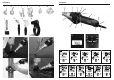
Tool description - Operation
Please note: The distance from the object you are working
on depends on material and intended method of working. Al-
ways try out the airflow and temperature on a test piece first.
Using the attachable accessory nozzles (see accessories
page on the cover) the flow of hot air can be controlled with
maximum precision.
Take care when changing hot nozzles! When using
the hot air tool in the self-resting position, make sure it is
standing on a stable, non-slip and clean surface.
1. Operation
The tool is switched on and off at the ON/OFF button
8
on
the back of the grip handle.
The joystick
9
is used for con-
trolling temperature and airflow or fan speed.
2. Setting the temperature
Temperature can be infinitely varied over a range of
50-700 °C at the joystick on the control panel with LCD dis-
play. The actual temperature is measured at the hot air outlet
nozzle and indicated on the display.
The joystick
9
is used as an input button with plus/minus function.
Briefly pressing the "+/–" joystick increases or reduces
the temperature setting in 10 ° steps. Keeping the joystick
pressed speeds up the temperature setting process. Once
the temperature has been set, the tool takes a few seconds
to reach temperature (depending on speed/airflow). The
temperature setting selected is shown on the display for 3
seconds. The display then shows the current actual temper-
ature. The "°C/°F" symbol continues to flash until the select-
ed temperature is reached.
If you want to alter the setting, simply press the joystick
again to increase or reduce the temperature. After switching
off, the hot air tool stays in the last setting.
3. Setting airflow rate
To change the airflow rate, first press the button for airflow
mode
10
; the fan symbol flashes. Now use the joystick to
set the airflow rate. The airflow rate setting mode automati-
cally closes if the airflow rate setting is not changed within 5
sec. Pressing the airflow button again after setting the airflow
rate immediately closes the airflow rate setting mode.
The
airflow rate can be varied from a minimum of 150 l/min to a
maximum of 500 l/min.
Temperature measurement on the workpiece
We recommend the STEINEL HG Scan PRO temperature
scanner (Prod. No.: 007553) for measuring the temperature
at the workpiece.
Programming mode [P]
Four programmes are factory-set for the most common
types of work. Press button "P" for programming mode.
Number 1 is displayed for programme 1. Continuing to
press the programme button will take you to programmes
2–4. Pressing the button again will return the tool to normal
operation.
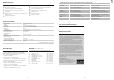
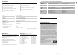
Preset programmes
Memory function [S]
The values selected for the four programmes can be
changed and memorised at any time. To do this, first press
the programme button "P"
11
until the display shows the
programme you wish to change. Set the temperature and
airflow rate you require. Memory symbol
on the LCD
flashes to indicate that the user programme selected has
been changed. To memorise this setting in the user pro-
gramme selected, press and hold down the programme
selector button. The memory symbol continues to flash for
approx. 2 sec. The settings entered are saved once the
memory symbol stays on all the time. To return to normal
operation, press the programme button until the programme
symbol disappears from the display.
Fine dust filter
The
HG 2620 E has an integrated fine dust filter
3
. To clean
it (with compressed air), undo screws (a), take off cover and
remove filter.
Changing the power cord
If the power cord is damaged, it can easily be changed with-
out opening the casing.
1. Important! Disconnect tool from power supply.
2. Undo screw
z
d
and pull off cover cap
z
a
.
3. Release cable grip
z
b
.
4. Undo mains terminals
z
c
.
5. Pull out cable
z
e
.
6. Insert new cable and secure in reverse order
(1. Firmly screw down mains terminals etc.).
Programme Temperature °C Air l/min
1 250 approx. 350
2 350 approx. 400
3 450 approx. 500
4 550 approx. 400
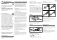
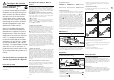
Changing the heating element
The plug-in heating element in the HG 2620 E can be
changed in a matter of seconds.
1. Important! Disconnect tool from power supply.
2. Undo guard sleeve screws (Fig.
1).
3. Remove guard sleeve (Fig. 1).
4. Undo 4 screws at the end of the hot air outlet nozzle (Fig. 2).
5. Detach heating element and replace it with a new one
(Fig. 2/3).
6. Firmly screw heating element into place (Fig. 3).
7. Firmly screw guard sleeve back on (Fig. 4).
Maintenance
Repair
a
a
14
3
1.
3.
2.
4.
Restart protection
Restart protection prevents the hot air tool from starting after
an interruption in the power supply. The hot air tool is only
ready for operation again after switching it on at the ON/OFF
button
8
.
LOC function
To avoid altering the chosen settings unintentionally, the
HG 2620 E comes with a Lockable Override Control
Function (LOC). To find out how to set the LOC function,
please contact our Service Department on
+44/1733/366-700.
Other functions