
User manual


– 12 – – 13 –
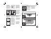
Safety warnings
Disconnect the power
before attempting any
work on the motion
detector.
The electrical connec-
tion lead must be dead
during installation.
Therefore, switch off the
power supply fi rst and
check that the circuit is
disconnected using a
voltage tester.
Installation of the sensor
involves work on the
mains power supply.
This work must therefore
be carried out profes-
sionally in accordance
with the applicable wiring
regulations and supply
conditions.
Please note that the sen-
sor must be protected
by a 10 A circuit breaker.
The mains supply lead
must be no greater than
10 mm in diameter.
Only carry out time and
light threshold settings
with the lens fi tted.
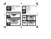
Principle
The IS 180-2 is equipped
with two 120° pyro sensors
which detect the invisible
heat emitted by moving
objects (people, animals
etc.). The heat detected
is electronically converted
into a signal that switches
on loads (e.g. a light) con-
nected to it. Heat is not
detected through obstacles,
such as walls or panes of
glass. Heat radiation of this
type will, therefore, not trig-
ger the sensor. With a 90°
angle of aperture, the two
pyro sensors cover a detec-
tion angle of 180°. The lens
can be removed and turned,
thereby permitting two max.
basic reach settings of 5m
or 12 m. Using the wall
mounts provided with the
unit, the infrared sensor can
easily be fi tted to internal
and external corners.
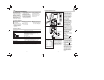
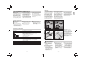
Important: The most
reliable way of detecting
motion is to install the unit
so that the sensor is aimed
across the direction in
which a person would walk
and by ensuring that no
obstacles (such as trees,
walls etc.) obstruct the line
of sensor vision.
Reach max. 12 m Reach max. 5 m
Direction of approach:
towards the sensor
Direction of approach:
across the detection zone
Installation instructions
Dear Customer,
Congratulations on purchas-
ing this STEINEL Infrared
Sensor and thank you for
the confi dence you have
shown in us. You have cho-
sen a high-quality product
that has been manufac-
tured, tested and packed
with the greatest care.
Please familiarise yourself
with these instructions
before attempting to install
the sensor since prolonged
reliable and trouble-free op-
eration will only be ensured
if it is installed properly.
We hope your new Infrared
Sensor will give you lasting
satisfaction.
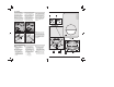
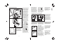
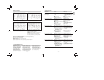
System components
Security screw
Front cover
Lens (can be removed
and turned for selecting
the max. basic reach set-
tings of 5 m or 12 m)
Light threshold setting
control 2 – 2000 lux
Time setting control
10 sec. – 15 min.
Clip (housing can be
fl ipped up for assembly
and connection to mains
power supply)
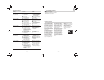
Dimensions: (H x W x D) 120 x 76 x 56 mm
Output:
Filament bulbs, 1000 W max., operating on 230 V AC
Fluorescent lamp, 500 W max., at cos ϕ = 0.5,
inductive load at 230 V AC
6 x 58 W each max., C ≤ 132 μF
operating on 230 V AC
*1)
Connection: 230 – 240 V, 50 Hz
Detection angle 180° horizontal, 90° vertical
Sensor reach: basic setting 1: 5 m max.
basic setting 2: 12 m max. (factory setting)
+ precision adjustment from 1 – 12 m by means
of clip-on shrouds
Time setting: 10 sec. – 15 min. (factory setting: 10 sec.)
Light threshold: 2 – 2000 lux (factory setting: 2000 lux)
Enclosure: IP 54
*1)
Fluorescent lamps, low-energy bulbs, LED lights with electronic ballast (total capacity of all connected
ballasts below the value specifi ed).
Technical specifi cations
GB