
User manual


– 14 – – 15 –
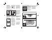
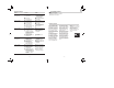
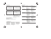
Functions
Once you have connected
the unit to the mains power
supply, closed the housing
and fi tted the lens, you are
ready to put the system
into operation. Two setting
controls are concealed
behind the front cover .
Important: Only carry out
time and light threshold
settings with the lens fi tted.
Switch-off delay
(time setting)
The chosen light ON time
can be varied continuously
from approx. 10 sec. to a
maximum of 15 min. Turning
the adjustment screw fully
anti-clockwise selects the
shortest time of approx.
10sec., turning the adjust-
ment screw fully clockwise
the longest time of approx.
15 min. The shortest time
setting is recommended
for setting the detection
zone and performing the
walk test.
Twilight setting
(response threshold)
The chosen detector
response threshold can be
adjusted continuously from
approx. 2 lux to 2000lux.
Turning the adjustment
screw fully anti-clockwise
selects daylight operation
at approx. 2000 lux. Turning
the adjustment screw fully
clockwise selects
twilight
operation at approx. 2 lux.
The adjustment screw
must be turned fully
anti-clockwise for setting
the detection zone and
performing the walk test in
daylight.
10 sec.-15. min.
2 - 2000 lux
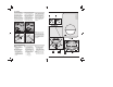
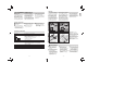
The corner wall mount
enclosed with the unit pro-
vides a convenient means
of installing the IS 180-2
to internal and external
corners. Use the corner wall
holder as a template for
drilling the hole. This way,
you will drill the hole at the
right angle, allowing you to
fi t the wall mount with ease.
Installation using corner wall mount
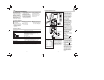
b) Connect service lead
The service supply lead
to the light is also a 2 to
3-core cable. Connect the
light’s current-carrying
conductor to the terminal
marked L’. The service lead
neutral conductor must be
connected to the terminal
marked N together with the
mains lead neutral conductor.
Connect the protective-
earth conductor to the
earth contact ( ).
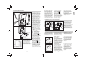
7. Screw on housing
and close again.
8. Fit lens (set reach to
either 5 m or 12 m max),
see ‘Reach setting’ section.
9. Select time and light
threshold setting (see
‘Functions’ section).
10. Locate front cover
and fi t security screw to
protect cover from unau-
thorised removal.
Important: Reversing the
connections may result in
damage to the unit.
The site of installation
should be at least 50 cm
from a light because heat
radiated from it may trigger
the sensor unintentionally.
To obtain the specifi ed
ranges of 5/12 m, the
sensor should be installed
at a height of approx. 2 m.
Installation procedure:
1. Detach front cover ,
2. Release clip and fl ip up
lower half of housing,
3. Mark drill holes, 4. Drill
the holes, insert wall plugs
(6 mm dia.), 5. Break open
cable entry for surface or
concealed wiring.
6. Feed through mains sup-
ply and service cable and
connect to terminals. Use
sealing plugs for surface
wiring.
a) Connect mains supply
lead
The mains supply leads is a
2 to 3-core cable:
L = phase conductor
N = neutral conductor
PE = protective-earth
conductor
If you are in any doubt, you
must identify the cables
using a voltage tester; once
you have done so, discon-
nect the power supply
again. Connect the phase
(L) and neutral conductor
(N) to the clamp-type ter-
minal. Connect the protec-
tive earth conductor to the
earth terminal ( ).
A power ON/OFF switch
may of course be installed
in the power supply lead.
Alternatively, you may use
a normally closed contact
pushbutton to activate the
sensor manually for the
duration of the time setting.
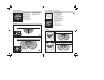
Note: The internal-corner
wall mount may be used
for mounting the sensor to
the wall. The cables can
be conveniently routed
down the surface of the
wall behind the unit and fed
through the cable entry.
Surface wiring
Mains supply lead
Service lead
Suppy cable
Surface wiring with wall mount
Concealed wiring
Installation/Wall mounting
GB