SI Cable HoISt ownerS’ Manual SI-60 and SI-75 Models Safety • operation • Installation • Parts Stellar Industries, Inc. Subject to Change without Notification. © 2012 Stellar Industries, Inc. 190 State Street PO Box 169 Garner, IA 50438 800-321-3741 Fax: 641-923-2811 www.stellarindustries.
Stellar Cable Hoist Manual Revisions Date of Revision Section Revised Description of Revision
Table of Contents Table of Contents Introduction...............................................................................iii Chapter 1 - Safety ...................................................................1 Chapter 2 - Operation.............................................................3 General Guidlines for Operation of the Cable Hoist ...........4 Loading Operation...................................................................5 Unloading Operation - O.R. and I.O. Models ...............
ii Stellar Cable Hoist Owner’s Manual AN OVERVIEW TO OWNER, OPERATOR AND SERVICE PERSONNEL ABOUT SAFETY As the owner or employer, it is your responsibility to instruct the operator in the safe operation of this equipment and to provide the operator with properly maintained equipment. FAILURE TO READ THIS MANUAL BY ANYONE WHO WILL OPERATE, SERVICE, OR WORK AROUND THIS CABLE HOIST IS A MISUSE OF THE EQUIPMENT. DEATH OR SERIOUS INJURY WILL RESULT FROM IMPROPER USE OR MAINTENANCE OF THIS MACHINE.
Introduction iii Introduction Stellar Cable hoists are designed to provide safe and dependable service for a variety of operations. With proper use and maintenance, these cable hoists will operate at peak performance for many years. To promote this longevity, carefully study the information contained in this manual before putting the equipment into service.
iv Stellar Cable Hoist Owner’s Manual
Safety 1 Chapter 1 - Safety Please Read the Following Carefully! This portion of the manual contains information regarding all Stellar manufactured Cable Hoists. Some items contained within this chapter may not apply to your specific equipment. Safety should be the number one thought on every operator’s mind. Three factors should exist for safe operation: a qualified operator, well-maintained equipment, and the proper use of this equipment.
2 Stellar Cable Hoist Owner’s Manual Do not move the truck while the hoist and container are raised. A raised load creates a top heavy unstable load. Do not use a chain between the reeving cable and the container. A chain will not withstand the force applied to the cable. Do not use any method to hold a valve open which will not let the valve close automatically when released. Always keep the cable centered on the hoist frame.
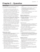
Operation Chapter 2 - Operation Job-Site Set-Up Thoroughly plan the lift before positioning the vehicle. Consider the following: 1. The vehicle should be positioned in an area free from overhead obstructions to eliminate the need for repositioning. 2. Position the vehicle so that it is impossible for any portion of the equipment to come within the minimum required safe distance of any power line.
4 Stellar Cable Hoist Owner’s Manual General Guidlines for Operation of the Cable Hoist Loading a Container 1. Back the truck up to the container to be loaded and align the hoist rails with the container long sills. Caution: Be sure the area in which the hoist is to be operated is clear of personnel and obstacles overhead and on the ground. 2. Engage the PTO and raise the hoist until the rear roller is on the ground. 3.
Operation Loading Operation 1 Back the truck up to the container to be loaded and align the hoist rails with the container long sills. 2 Engage the PTO and raise the hoist until the rear roller is on the ground. 3 Set the parking brakes and retract the reeving cylinders to connect the cable to the container. 4 Release the parking brake and allow the truck to roll under the container. Extend the reeving cylinders to pull the container onto the hoist.
6 Stellar Cable Hoist Owner’s Manual Unloading Operation - O.R. and I.O. Models 1 Back the truck up in front of where the container is to be spotted. Allow room for the container to roll-off of the hoist. 2 Raise the hoist and retract the reeving cylinders. Allow gravity to pull the container to the ground. 3 Once the rear rollers are on the ground, allow the truck to roll out from under the container.
Operation Unloading Operation - Extendable Tail Models 1 Back the truck up in front of where the container is to be spotted. Allow room for the container to roll-off of the hoist. 2 Raise the hoist and retract the reeving cylinders. Allow gravity to pull the container to the ground. Once the rear rollers are on the ground, allow the truck to roll out from under the container. 3 Alternate extending the cable and the tail until the container is on the ground.
8 Stellar Cable Hoist Owner’s Manual Correct Roll-Off Container Loads Correct Container Position Correct Position For Short Container Note: Removable front stops must be used and rear hold downs must match on container and roll-off hoist. Unsafe Roll-Off Container Loads The Container is Too Long Frame may crack or bend. Load Center is Too Far to the Rear Front Axle May Be Too Light Frame may crack or bend. Frame may crack or bend. Front Axle May Be Overloaded Frame may crack or bend.
Operation Hoist Prop Operation WARNING BEFORE WORKING AROUND A RAISED HOIST, THE HOIST MUST BE SUPPORTED BY THE HOIST PROP. (SEE HOIST PROP OPERATING INSTRUCTIONS) FAILURE TO DO SO COULD RESULT IN SERIOUS INJURY OR DEATH. IF THE HOIST PROPS CANNOT BE USED, CONSULT THE MAINTENANCE SECTION OF THE OPERATION MANUAL FOR THE PROPER PRECAUTIONS.
10 Stellar Cable Hoist Owner’s Manual
Maintenance 11 Chapter 3 - Maintenance Please read the following before performing any maintenance on the Cable Hoist. 1. Only authorized service personnel are to perform maintenance on the Cable Hoist. 2. Disengage the PTO before any service or repair is performed. 3. Do not disconnect hydraulic hoses while there is still pressure in those components. 4.
12 Stellar Cable Hoist Owner’s Manual Inspection of Sheaves Under normal conditions, machines should receive periodic inspections, and their overall condition recorded. Such inspections usually include the sheaves, and any other parts that may come into contact with the wire rope and subject it to wear. As an additional precaution, rope related working parts, particularly in the area described below, should be re-inspected prior to the installation of a new cable.
Maintenance 13 Cable Replacement Important: Standard replacement cable must be 7/8” diameter 6 x 37 extra improved plow steel with steel core (6 x 37 EXIWRC) with a 4.00” swaged button x 75’ (174” & 182” CT, or) 77 feet (194” CT) in length. 1. Remove the cable clamps and discard the old cable. 2. Inspect all the sheaves (See Inspection of Sheaves on page 12). 3. Install cable end onto cable. Thread cable through sheaves and guides, etc.
14 Stellar Cable Hoist Owner’s Manual Choice Lubricants for DX Bearings Type of Grease Premium Quality Multi-Purpose Multi-Purpose Anti-Friction Bearing Extreme Pressure (EP) High Temperature Transmission Molybdenum Filled Graphite Filled Block Grease White Grease Silicone Type of Grease Cup Grease Graphite Filled Molybdenum Filled Fluorocarbon White Grease Greases Recommended Description Stabilized, Anti-Oxidant Lithium Base Lithium Base with 3% Molybdenum Disulfide High Drop Point Calcium Based, fo
Specifications Chapter 4 - Specifications Chassis C.T.: See chart on next page. Frame Width: 35-1/2” Minimum GVWR: 18,000 lbs. Front, 44,000 lbs. Rear Frame Height: 43” Sub-Frame: Full length 2 x 4 Tube Load Rating: 60,000 lbs., 75,000 lbs. Dump Angle: 47º Operating Pressure: 1,850 PSI (60,000 lbs), 2,150 PSI (75,000 lbs) Gear Pump: 35 GPM @ 1,500 RPM Operation: Inside Cab Cable Controls Standard Weight: 6,400 lbs. - 7,400 lbs.
16 Stellar Cable Hoist Owner’s Manual Cable Hoist Dimensions Specifications Chart CT (Cab to Trunnion) Models A B C D w/o Autotarper w/ Autotarper SI-60-174 OR/IO 281” 210” 174” 35.5” 174” 180” SI-60-182 OR/IO 289” 218” 174” 35.5” 182” 188” SI-60-194 OR/IO 301” 230” 186” 35.5” 194” 200” CT (Cab to Trunnion) Extended Tail Models A B C D w/o Autotarper w/ Autotarper SI-60-174 ORX 237” 210” 174” 35.5” 174” 180” SI-60-182 ORX 245” 218” 174” 35.
Specifications Container Subframe NOTE: ALL DIMENSIONS ARE IN ACCORDANCE WITH ANSI Z245.60 TYPE "U" CONTAINER REQUIREMENTS FRONT VIEW MAX. 41.00 GUIDE ROLLER GROUND WHEEL MIN. 3.38 MAX. 3.63 TYPICAL REAR HOLDDOWN LEAD-IN-ROLLER 2" X 6" STANDARD STRUCTURAL TUBING PICKUP HOOK SIDE VIEW MIN. 6.00 MAX. 10.50 MIN. 3.38 MAX. 3.63 MIN. 18.50 MAX. 24.00 MAX. 2.13 193.00 *SEE NOTE* GROUND WHEEL *LONG RAIL LENGTH* *NOTE* IF LONG RAIL LENGTH IS GREATER THAN OR EQUAL TO 12FT.
18 Stellar Cable Hoist Owner’s Manual
Decals Chapter 5 - Decals Decal Kit Placement 11 17 16 12 18 24 7 16 16 3 10 13 14 19 Item 1 2 3 4 5 6 7 PN 45702 45701 16094 46657 45981 46071 45553 Description TAPE CONSPICUITY YELLOW 9.00 IN a TAPE CONSPICUITY RED 9.00 IN b DECAL STELLAR LOGO5.00X13.
20 Stellar Cable Hoist Owner’s Manual Safety Decals of Note WARNING CRUSHING HAZARD Moving parts can crush and cut. Keep hands and arms clear. 25627 WARNING BEFORE WORKING AROUND A RAISED HOIST, THE HOIST MUST BE SUPPORTED BY THE HOIST PROP. (SEE HOIST PROP OPERATING INSTRUCTIONS) FAILURE TO DO SO COULD RESULT IN SERIOUS INJURY OR DEATH. IF THE HOIST PROPS CANNOT BE USED, CONSULT THE MAINTENANCE SECTION OF THE OPERATION MANUAL FOR THE PROPER PRECAUTIONS.
Installation 21 Chapter 6 - Installation General Install Guidelines Cable Hoist Mounting and Assembly Study names and locations of the parts and familiarize yourself with the Cable Hoist before starting the assembly . Reading the step-by-step instructions that follow will be helpful. Safety Read all of the safety notations in the assembly instructions for your protection. Accidents can be prevented by recognizing the cause of an accident before it can happen.
22 Stellar Cable Hoist Owner’s Manual Truck Chassis Specifications See the illustrations on pages 15-17 at the front of this manual for specific details. Front: 18,000 lbs. Rear: 44,000 lbs. with walking beam type suspension Total RBM per frame rail = 2,400,000 in-lbs.
Installation Dimensions: 174 Models Dimensions To Chassis Frame Rail 9 - 9/16 Forward Mount 11 2 - 1/4 281 - 1/4 8 - 9/16 24 86 - 1/2 26 - 5/8 87 - 7/16 9 25 - 13/16 21 - 3/4 55 174 C.T. 14 Rearmost Axle To First Cut 43 Chassis Frame Height 206 - 15/16 Dimensions To Chassis Frame Rail 11 2 - 1/4 Reverse Mount 9 - 9/16 281 - 1/4 26 - 5/8 176 - 3/4 9 68 - 7/8 107 - 7/8 8 - 9/16 25 - 13/16 21 - 3/4 55 174 C.T.
24 Stellar Cable Hoist Owner’s Manual Dimensions: 182 Models Dimensions to Chassis Frame Rail 9 - 9/16 2 - 1/4 Forward Mount 11 289 - 1/4 32 8 - 9/16 86 - 1/2 87 - 1/2 26 - 5/8 9 25 - 13/16 21 - 3/4 14 Rearmost Axle to First Cut 43 Chassis Frame Height 55 182 C.T. 214 - 15/16 Dimensions to Chassis Frame Rail 2.22 11.00 Reverse Mount 9.56 289 - 1/4 26 - 5/8 8 - 9/16 176 - 3/4 9 107 - 7/8 86 - 1/2 25 - 13/16 14 Rearmost Axle to First Cut 21 - 3/4 43 Chassis Frame Height 55 182 C.
Installation Dimensions: 194 Models Dimensions to Chassis Frame Rail 9 - 9/16 Forward Mount 11 2 - 1/4 301 - 1/4 44 8 - 9/16 86 - 1/2 9 87 - 7/16 25 - 13/16 21 - 3/4 55 194 C.T. 43 Chassis Frame Height 14 Rearmost Axle to First Cut 226 - 15/16 Dimensions to Chassis Frame Rail 11 2 - 1/4 Reverse Mount 9 - 9/16 301 - 1/4 8 - 9/16 23 - 9/16 26 - 5/8 176 - 3/4 9 86 - 1/2 21 - 3/4 25 - 13/16 43 Chassis Frame Height 14 Rearmost Axle to First Cut 55 194 C.T.
26 Stellar Cable Hoist Owner’s Manual Step 2: Mount Hoist Note: Refer to the illustration on the previous pages. A. Position the hoist sub-frame onto truck frame, aligning and squaring up with truck frame, clamp and then heavily tack in place. B. Continue to fully weld the hoist rear apron to the truck frame. Weld 100% 3/8” weld both sides of truck frame to hoist sub-frame: A W=.38 TYP. (2) TYP. (2) .38 DETAIL A SCALE 1 : 8 (.25) .38 .38 .38 TYP. (2) 6 TYP. (2) .38 .38 TYP. (2) .38 C.
Installation 27 Step 3: Mount Lift Cylinders A. Check frame for bolts, rivets, etc. and clearance required (Refer to the previous pages) before placing the Lift Cylinder Weldment into place under the hoist sub-frame. B. Install the cylinder weldment cross tube. C. Install the Lift Cylinders and extend each cylinder rod 1/4”. Check the shaft to cylinder dimension on both sides. Standard Lift Cylinders dimension should be 88 1/4” plus or minus1/8”.
28 Stellar Cable Hoist Owner’s Manual Mount Lift Cylinders Continued... E. Bolt the Lift Cylinder Weldment to the truck frame using the supplied hardware. F. (FORWARD MOUNT ONLY) Weld the Lift Cylinder Weldment to the sub-frame as shown in Figure C. Remove any gap between the weldment and sub-frame before welding. FRONT TYP 2 0.38 4-7.63 G. Make sure the cylinder cross tube is centered. Weld the cylinder cross tube. (See Figure B) NOTE: Do not weld to truck frame.
Installation 29 Step 5: Sub-Frame Front Clamp Installation Before proceeding any further, it is necessary to raise the hoist and set it down on the hoist props. 1. Position the L-shaped clamp between the sub-frame and truck frame as shown below. 2. Assemble the lower clamp and two (2) shims with a 5/8NC x 2-1/2” GD. 5 Cap Screw, two (2) Flat Washers 1 and Self Locking Nuts. Trim the lower clamp as required to clear the frame channel. Note: Stair-step the shims so fillet welds can be applied. 3.
30 Stellar Cable Hoist Owner’s Manual Step 7: Hydraulic Relief Pressure Setting 1. Locate the pressure gauge facing front of truck. 2. Loosen Jam Nut. 3. Using allen wrench, adjust to proper pressure. See Chapter 4: Specifications for pressure specifications. 4. Tighten Jam Nut, holding adjustment screw in position. 5. Test unit for proper operation, readjust to correct pressure if needed. 6. Retest unit checking leaks and proper operation.
Installation 31 Cable Control Installation Continued... 5. Choose a mounting location which is convenient and comfortable for the operator and provides adequate clearance for the control lever movement. Check the underside of the cab for reinforcement members, air lines, wiring harnesses, and linkages before cutting into the floor. Be sure the location chosen allows the cable to be led easily away from the control. Reversing control direction usually is not necessary.
32 Stellar Cable Hoist Owner’s Manual Step 9: Pneumatic Control Installation The pneumatic controller provided with the Stellar Cable Hoist are dual three-way regulating valves. Output of the controllers is proportional to the control lever position and is balanced against the force of an internal spring. Pneumatic Actuator Installation: The pneumatic actuator has been partially assembled and pre-lubricated for ease of installation. The actuator does not have to be disassembled for installation. 1.
Installation 33 Pneumatic Control Installation Continued... Pre-Assembled Pneumatic Control Tower Installation 1. Determine a suitable location which is in a comfortable location for the driver and not in the way of the transmission lever. 2. Position the lower bolt holes so that the bolts will miss any cable, wires or structural members in or under the cab floor. 3. Mark and drill the four (4) 3/8” diameter holes for the 3/8” x 1-1/2” cap screws supplied for the tower. 4.
34 Stellar Cable Hoist Owner’s Manual Step 10: Bumper Installation Lighted Bumper Installation 1. Align the holes in the lighted bumper with the holes in the hoist sub-frame apron. 2. Install six (6) 5/8NC x 1-3/4” GD.8 Cap Screws, twelve (12) Flat Washers, and six (6) Hex Nuts. Torque to specifications. 3. Install wiring harness P/N 38056 through the access hole. 4. Install the bumper lights as shown on parts pages 59-60. 5.
Installation 35 Bumper Installation Continued... I.C.C. Bumper Installation 1. Connect the bumper weldment to the hoist with two (2) 3/4NC x 4-1/2” Cap Screws, Spacers, Flat Washers and Self-Locking Nuts. It may be necessary to use Flat Washers between the bumper uprights and the hoist frame. 2. Connect the lower links between the pivot on the lighted bumper and the ICC bumper. Use a 3/4NC x 2-1/2” GD.5 Cap Screw, Spacer, Flat Washer and Self Locking Nut to attach each link to the lighted bumper.
36 Stellar Cable Hoist Owner’s Manual Step 11: Hoist Up Light Installation Locate bracket on hoist base. Tighten Dump Up Light Kit to the bracket. Installed PN 31806 DUMP UP LIGHT KIT BUYERS SK10 BRACKET SHOWN AS REFERENCE Note: See Electrical Schematic in the Hydraulic-Electrical Chapter for wiring diagram.
Installation Step 12a: Fender Installation - Steel Tandem/Tri-Axle Steel Tandem/Tri-Axle Position fender to allow for max air bag travel and spring compression. Position fender to allow for max walking beam travel. Position fender to allow adequate clearance between fender & hydraulic cylinder in upright extended position. 0.25” Weld Around (6 Places) 5/8NC Self Locking Nut Gusset Rear Fender Tube Weldment Spacer 1” x 2.5” x 2.
38 Stellar Cable Hoist Owner’s Manual Step 12b: Fender Installation - Plastic Tandem/Tri-Axle Plastic Tandem/Tri-Axle Match drill fenders and attach 3/8” bolt, flat washers and locknut. Weld front braces to cylinder mounting plate. Weld rear fender mounts to bumper. Weld on end caps. (8) Weld center support to sub-frame. After fender has been located properly, locate and weld fender support. Notch out if needed. Position fender to allow for max walking beam travel.
Installation Step 14a: Removable Stop Installation 1 1.1 .44” 2” 2” 7.1 ” 5 3.2 . .O I d n r t fo Slo a R. . O 7 27 able 7 4 v PN emo p R R. Sto . O 5” 3.2 En 6 27 ble 7 4 va PN mo Re top . S I.
40 Stellar Cable Hoist Owner’s Manual Step 14b: Intermediate Stop Installation 47272 I.O. Fold Down Stop .38 Fillet Weld (Weld Both Sides, Do not Weld Ends) Outside Face of Hoist Frame En do Cu f Tor t S ch lot PN 45621 O.R. Fold Down Stop .
Installation Step 15: Reflective Tape Installation REF. ANSI Standard Z245.1-1999 Z.2.16 Vehicle Conspicuity PN 63907 (Both Sides - No Tarper) 54” 18” 24” 2 24 6” PN 63907 (Both Sides - With Tarper) 36” 6” 12” 36” 12” 6” 18” 24” Back (All models) 60” Install full width ICC Bumper as shown. NOTE: Reflective tape locations and lengths are for reference. Your reflective tape location may differ due to equipment options.
42 Stellar Cable Hoist Owner’s Manual
Hydraulics - Electrical Chapter 7 - Hydraulics - Electrical Hydraulic Schematic F1 F E1 E Auxilary Cylinder Extender Cylinder Reeving Cylinder Control Valve E1 C D F1 Auxilary E Reeving Cylinder F Ext.
44 Stellar Cable Hoist Owner’s Manual Hydraulic Routing - Standard Lift Cylinder Standard Cylinder Mount
Hydraulics - Electrical Hydraulic Routing - Telescopic Lift Cylinder Telescopic Cylinder Mount 45585 45
46 Stellar Cable Hoist Owner’s Manual Hydraulic Routing - Reverse Mount Lift Cylinder Reverse Cylinder Mount
Hydraulics - Electrical Reverse Mount Lift Cylinder Mounting Kit - PN 56094 Part 1 NOTE: PN:45143 ALWAYS WELDED ON STREET SIDE .75 6.19 .19 .19 TYP. 2 .19 1.50 TYP. 2 4.00 TYP.
48 Stellar Cable Hoist Owner’s Manual Reverse Mount Lift Cylinder Mounting Kit - PN 56094 Part 2 NOTE: CABLE HOIST SHOWN AS REFERENCE 10 PN 56094 ITEM 1 PART 45585 2 64064 DESCRIPTION QTY. FTG TEE JIC 12 JTX-S 2 HOSE 0.75(471TC-06-39-12-12-122 60) HOSE 0.75(471TC-06-39-12-12-12- 2 70) 3 64065 4 45948 U BOLT 0.31X1.50X2.25 RD 4 5 45143PC 3381PC 7 0343 PLATE 0.25X3.00X5.75 HOSE CLAMP BOLT ON 1210 CRANE WASHER 0.31 USS FLAT ZINC 1 6 10 8 C0927 CAP SCR 0.31-18X2.
Hydraulics - Electrical Hydraulic Routing - Reeving Cylinder Reeving Cylinder 49
50 Stellar Cable Hoist Owner’s Manual Hydraulic Routing - Tail Extension IOX Cylinder Mount Tail Extension IOX Cylinder Mount
Hydraulics - Electrical 51 Hydraulic Routing - Tail Extension ORX Cylinder Mount Tail Extension ORX Cylinder Mount
52 Stellar Cable Hoist Owner’s Manual Electrical Schematics EXISTING TRUCK WIRING HARNESS BACK-UP LIGHT (BLACK) TRUCK CAB LH, TURN, BRAKE, LIGHT (YELLOW) TAIL, CLEARANCE, LIGHT (BROWN) HOIST UP LIGHT WHITE REMOTE SWITCH GROUND (WHITE) RH, TURN, BRAKE, LIGHT (GREEN) COLORED Note: The Hoist Up Light will only be activated when the iginition is hot. It is recommended to tap into the PTO light power source when wiring.
Assembly Drawings 53 Chapter 8 - Assembly Drawings Cable Controls Qty. Qty.
54 Stellar Cable Hoist Owner’s Manual Air Controllers Assembly 1 Item PN Qty. Item PN 1 C1002 CAP SCR 0.50-13X6.00 HHGR5 3 16 0523 WASHER 0.38 LOCK 4 2 C6106 NUT 0.50-13 HHGR5 NYLOC 1 17 0535 NUT 0.
Assembly Drawings 55 Air Controllers Assembly 2 2 Section Air PN 45833 ITEM 1 2 3 4 5 1 2 PART 45307 0345 0346 0523 0535 DESCRIPTION CONTROL TOWER ASM 2SECT AIR K-PAC CAP SCR 0.38-16X1.50 HHGR5 WASHER 0.38 USS FLAT ZINC WASHER 0.38 LOCK NUT 0.38-16 HHGR5 QTY.
56 Stellar Cable Hoist Owner’s Manual Main Hoist Assembly 2 45 29 27 3 16 49 44 39 7 28 34 6 4 37 41 7 34 37 24 24 22 31 21 42 4 33 6 41 24 25 12 48 NOTE: 30 - DECALS MUST BE BELOW TOP OF ROLLERS 30 5 - ALL ROLLERS AND SHEAVES MUST MOVE FREELY 4 18 20 36 35 21 48 34 38 48 31 32 1 9 46 11 47 32 30 26 10 32 23 15 31 32 4 19 17 43 32 40 13 14 ITEM 1 2 3 4 5 6 7 8 9 10 11 12 13 14 15 16 17 18 19 20 21 22 23 24 PART 0335 0345 0346 0347 0351 0352 0359 0427 05
Assembly Drawings 57 Reeving Cylinder Assembly - PN 60219 174 and 182 Models 7 8 PN 60219 1 10 12 ITEM 1 2 3 4 5 6 7 8 9 10 11 12 13 14 15 16 17 18 17 18 2 16 9 11 10 14 15 10 PART 45243 45114 8621 0346 0347 45551 19371 18701 45585 C4498 58391 58392 58389 58390 45590 2828 45623 c1592 DESCRIPTION CYLINDER 7.00X80.00 KPAC REEVING SHEAVE WLDMT KP60 CLAMP HOSE/TUBE AG-3 WASHER 0.38 USS FLAT ZINC NUT 0.38-16 HHGR5 NYLOC BOLT CARRIAGE 0.38-16X3.00 HOSE CLAMP 7.13-10.
58 Stellar Cable Hoist Owner’s Manual Chassis Mounted Parts
Assembly Drawings 59 Chassis Mounted Parts Item PN Description Qty. 1 45054 SUB-FRAME FRONT WELDMENT 1 2 45059 SUB-FRAME FRONT WELDMENT 1 3 46134 PLATE SUBFRAME EXTENDER CLAMP 2 4 46062 MOUNTING BRACKET RSRVR SI60 2 5 46063 TUBE RSRVR MOUNTING SI60 2 6 45600 MOUNT BRKT TRUCK FRAME LUG SI60 2 7 47089 NUT 0.63-18 HHGR5 NYLOC 2 8 C1038 WASHER 0.
60 Stellar Cable Hoist Owner’s Manual Mounting Kit (Forward Mount) - PN 55261 9 8 11 6 7 4 10 NOTE: USE REAR HOLE TO BOLT CYLINDER PIN WLDMT 1 PN 55261 3 5 4 2 ITEM 1 2 3 4 5 6 7 8 9 10 11 12 12 PART 49997 49995ZP 0500 C6106 0352 55262 45756PC 1593 0507 52889PC 52892PC 31680 DESCRIPTION TUBE 5.00X3.00X0.38WX56.00 PIN WLDMT CYL MNT CABLE75 CAP SCR 0.50-13X1.75 HHGR5 NUT 0.50-13 HHGR5 NYLOC WASHER 0.50 USS FLAT ZINC CYLINDER ASM 6.00X72.00 LIFT CABLE75 MNT COLLAR 2.51X3.50X1.
Assembly Drawings 61 Mounting Kit (Reverse Mount) - PN 56094 8 9 11 6 7 4 10 NOTE: USE REAR HOLE TO BOLT CYLINDER PIN WLDMT 1 PN 56094 12 2 3 5 ITEM 1 2 3 4 5 6 7 8 9 10 11 12 4 PART 49997 49995ZP 0500 C6106 0352 55262 45756PC 1593 0507 52889PC 52892PC 31680 0.25 0.25 TYP. 2 TYP. 4 0.25 0.25 0.19 1.00 TYP. 4 TYP. 2 DESCRIPTION TUBE 5.00X3.00X0.38WX56.00 PIN WLDMT CYL MNT CABLE75 CAP SCR 0.50-13X1.75 HHGR5 NUT 0.50-13 HHGR5 NYLOC WASHER 0.50 USS FLAT ZINC CYLINDER ASM 6.00X72.
62 Stellar Cable Hoist Owner’s Manual Mounting Kit (Telescopic) - PN 55265 11 9 8 10 6 7 4 12 1 13 2 3 5 4 PN 55265 ITEM 1 2 3 4 5 6 7 8 9 10 11 12 13 PART 49997 49995ZP 0500 C6106 0352 51078 45756PC 1593 0507 52889PC 52892PC 31680 55320 DESCRIPTION TUBE 5.00X3.00X0.38WX56.00 PIN WLDMT CYL MNT CABLE75 CAP SCR 0.50-13X1.75 HHGR5 NUT 0.50-13 HHGR5 NYLOC WASHER 0.50 USS FLAT ZINC CYLINDER ASM 5.50X185.75 TELO KPAC COLLAR 2.51X3.50X1.50 W/HOLE MACHY WASHER 2.50ID 10GA CAP SCR 0.50-13X4.
Assembly Drawings 63 Cab Guard - PN 47263 1 4 2 6 3 7 4 5 Adjust position on truck frame to protect window & back of cab. Square cab guard with truck frame, clamp to truck frame using shims if needed. Drill three (3) 5/8" holes through cab guard and truck frame approx. 3" apart (both sides). Bolt cab guard to truck frame. FRAME RAIL PN 47263 ITEM 1 2 3 4 5 6 7 PART 47262 47265 47264 2826 2827 C0964 C1038 DESCRIPTION CAB GUARD WLDMT KP60 FLAT 0.25X2.00X10.50 CLAMP BAR CAB GUARD KP60 NUT 0.
64 Stellar Cable Hoist Owner’s Manual Under Body Tool Box - PN 46579 1 8 9 10 3 5 4 12 4 6 2 7 7 2 13 PN 46579 ITEM 1 2 3 4 5 6 7 8 9 10 11 12 13 PART 46580 46578PC 46577 0352 0359 C6106 46590 22045 4110 23763 4183 4167 16333 DESCRIPTION QTY. UBTB WLDMT OH 20X48X15 1 UBTB MNT WLDMT 15.00D-KPAC 2 DOOR OH 16.19X40.06 VECTOR SPT-KPAC 1 WASHER 0.50 USS FLAT ZINC 8 CAP SCR 0.50-13X1.50 HHGR5 4 NUT 0.50-13 HHGR5 NYLOC 4 CAP SCR 0.50X1.
Assembly Drawings 65 Reservoir Assembly - PN 46133 5 4 RETURN PORT FACING THIS SIDE 3 10 9 6 1 2 7 8 PN 46133 ITEM 1 2 3 4 5 6 7 8 9 10 PART 46130 15463 45075 C6353 0335 15464 C4845 C6327 57739 58396 DESCRIPTION RSRVR WLDMT 60GAL KP60 THERMO SIGHT GAUGE FILTER K-PAC TANK TOP WASHER 0.38 SAE FLAT YELLOW GR8 CAP SCR 0.38-16X1.25 HHGR5 TANK COVER PLUG 0.75 NPT SQ HD BLK FILTER STRAINER 35GAL TF-2030 CAP FILL ASM W/3” NECK 1PSI GASKET RG-11 TANK TOP FILTER QTY.
66 Stellar Cable Hoist Owner’s Manual 2 Section Valve Bank Reservoir - PN 45710 24 5 16 7 11 12 25 21 6 1 10 26 17 2 27 3 8 24 4 18 19 23 13 12 15 13 14 15 24 PN 45710 ITEM 1 2 3 4 5 6 7 8 10 11 12 13 14 15 16 17 18 19 20 21 22 23 24 25 26 27 PART 46133 D1306 30541 9758 C2282 D0652 45831 C4750 59841 C0954 0346 0347 45802 C4498 8617 C0953 C6353 6397 46063PC 7285 C1123 16333 46590 c4819 17766 C4730 DESCRIPTION RSRVR ASM 60GAL KP60 FTG ADAPT MSTR/FSTR 16-12 F5OG5 FTG ADAPT 12-1/4 F5OG
Assembly Drawings 67 3 Section Valve Bank Reservoir - PN 46642 22 14 9 3 5 11 21 12 27 23 4 25 1 18 28 26 8 6 2 7 25 10 20 24 19 12 15 13 16 17 PN 46642 ITEM 1 2 3 4 5 6 7 8 10 11 12 13 14 15 16 17 18 19 20 21 22 23 24 25 26 27 28 PART 46133 9758 C2282 D0652 45831 C4750 D1306 30541 59843 C0954 0346 0347 8617 45802 D1189 C4498 C0953 C6353 6397 46063PC C1123 7285 46590 16333 C4730 c4819 17766 DESCRIPTION RSRVR ASM 60GAL KP60 FTG ST TH-F PIPE EL 90 6805-20-20 FTG 1.25 NPT TO 1.
68 Stellar Cable Hoist Owner’s Manual Reservoir Mounting Bracket for PN 45710 3 5 4 1 For Reservior PN 45710 ITEM 1 2 3 4 5 PART 46062PC 46063 10662 5468 D0790 2 DESCRIPTION MOUNTING BRACKET RSRVR KP60 TUBE RSRVR MOUNTING KP60 CAP SCR 0.50-13X2.50 HHGR8 NUT 0.50-13 HHGR8 NYLOC WASHER 0.50 SAE FLAT YELLOW GR8 QTY 2 2 12 12 24 3 5 4 1 2 For Reservior PN 46642 ITEM 1 2 3 4 5 PART 46062PC 46063 10662 5468 D0790 DESCRIPTION MOUNTING BRACKET RSRVR KP60 TUBE RSRVR MOUNTING KP60 CAP SCR 0.50-13X2.
Assembly Drawings 69 Standard Lighted Bumper - PN 45887 17 14 20 19 19 9 12 12 11 4 3 16 8 6 10 9 15 18 13 5 2 7 19 12 3 1 PN 45887 ITEM PART DESCRIPTION QTY. 1 0335 CAP SCR 0.38-16X1.25 HHGR5 8 2 0340 WASHER 0.25 FLAT 8 0346 WASHER 0.38 FLAT 16 3 4 0347 NUT 0.38-16 HH NYLOC 8 5 0480 CAP SCR 0.25-20X1.00 HHGR5 4 0533 NUT 0.25-20 HH 4 6 7 0654 NUT 0.25-20 WING 4 8 2320 LICENSE PLATE LIGHT ROUND 430 W 1 9 10334 GROMMET 4.00 ROUND LAMP (PETERSON) 7 10 11693 CAP SCR 0.63-11X1.
70 Stellar Cable Hoist Owner’s Manual Pintle Bumper - PN 46818 18 7 3 7 8 11 9 2 8 8 16 8 17 4 3 12 7 15 13 15 14 9 10 PN 46818 ITEM 1 2 3 4 5 6 7 PART 62293 45039PC 13145 2320 27626 13143 C4862 8 10334 9 10 11 12 13 14 15 16 17 18 0346 0335 0347 0480 0533 0654 0340 C0073 18742 46822 DESCRIPTION BUMPER WLDMT 90K PINTLE TARPER PLATE MUD FLAP BACKING 43"FENDER KP LIGHT CLEARANCE RED RND 2 LED LICENSE PLATE LIGHT ROUND 430 W LIGHT BACKUP LED 62391 LIGHT STOP/TURN/TAIL 4 RND LED GROMMET F
Assembly Drawings 71 ICC Wide Bumper - PN 53397 5 7 4 4 7 2 4 3 6 1 PN 53397 ITEM 1 2 3 4 5 6 7 PART 53398 45813PC 45815 C6219 C0538 58681 5841 DESCRIPTION BUMPER WLDMT ICC WIDE PLATE LINK ICC BUMPER SPACER 1.25ODX0.75IDX2.16 WASHER 0.75 SAE FLAT YELLOW GR8 NUT 0.75-10 HHGR8 NYLOC CAP SCR 0.75-10X2.50 HHGR8 CAP SCR 0.75-10X4.50 HHGR8 QTY.
72 Stellar Cable Hoist Owner’s Manual ICC Heavy Duty Bumper - PN 46809 3 2 5 4 1 PN 46809 ITEM 1 2 3 4 5 PART 46804 46877PC 5223 46810 46811 DESCRIPTION BUMPER WLDMT ICC HEAVY DUTY KPAC PIVOT BLOCK WLDMT ICC KP60 NUT 1.25-7 HHGR5 NYLOC PIN SNAP LOCK 1.00 KPAC 60-406 CAP SCR 1.25-7X5.50 HHGR5 QTY. 1 2 2 2 2 .31 W=.47 TYP. 4 21.51 22.00 (.31) TYP.
Assembly Drawings 73 ICC Bumper Weldment - PN 45574 4 3 TYP(2) .25 TYP (2) .19 1 2 19.00 16.00 15.44 TYP(2) .25 35.50 66.38 PN 45574 ITEM 1 2 3 4 PART 45572 43138 45573 21447 DESCRIPTION TUBE 3.00X2.00X0.25WX66.00 PLATE 0.19X2.63X1.63 TUBE 3.00X2.00X0.25WX22.63 TUBE 3.00X2.00X0.25WX14.00 QTY. 1 2 2 2 (.31) 22.00 TYP. 4 THREE SIDES OF TUBE .25 W=.47 TYP.
74 Stellar Cable Hoist Owner’s Manual ICC Standard Narrow Bumper - PN 48848 6 20 3 13 14 8 19 9 18 15 16 17 12 5 9 3 6 4 10 11 2 3 PN 48846 ITEM 1 2 3 4 5 6 7 8 9 10 11 12 13 14 15 16 17 18 19 20 PART QTY. 48849 DESCRIPTION BUMPER WLDMT STANDARD KP60 NRW ICC 27626 LIGHT BACKUP LED 62391 13145 LIGHT CLEARANCE RED RND 2 LED 13143 LIGHT STOP/TURN/TAIL 4 RND LED 10334 GROMMET 4.
Assembly Drawings 75 ICC Narrow Bumper - PN 48846 1 4 5 5 3 4 5 5 6 2 6 3 5 6 5 5 7 PN 48846 ITEM 1 2 3 4 5 6 7 PART 48847 45813PC 45815 5841 C6219 C0538 58681 DESCRIPTION BUMPER WLDMT ICC NARROW KPAC PLATE LINK ICC BUMPER SPACER 1.25ODX0.75IDX2.16 CAP SCR 0.75-10X4.50 HHGR8 WASHER 0.75 SAE FLAT YELLOW GR8 NUT 0.75-10 HHGR8 NYLOC CAP SCR 0.75-10X2.50 HHGR8 QTY.
76 Stellar Cable Hoist Owner’s Manual ICC Extendable Bumper - PN 62663 4 7 5 3 6 1 2 PN 62663 ITEM 1 2 3 4 5 6 7 PART 62664PC 45813PC 45815 45623 C0538 58681 C6219 DESCRIPTION BUMPER WLDMT ICC STANDARD EXT PLATE LINK ICC BUMPER SPACER 1.25ODX0.75IDX2.16 CAP SCR 0.75-10X4.50 HHGR5 NUT 0.75-10 HHGR8 NYLOC CAP SCR 0.75-10X2.50 HHGR8 WASHER 0.75 SAE FLAT YELLOW GR8 QTY.
Assembly Drawings 77 Tri-Axle Fenders - PN 46299 NOTE: Includes PN 46122 Tandem Fenders 1 6 7 3 4 2 5 8 PN 46299 ITEM 1 2 3 4 5 6 7 8 PART 46626 45039PC 46627PC 0347 0351 0537 46590 C4821 DESCRIPTION QTY. STD FEND WELDMENT-48" 2 PLATE MUD FLAP BACKING 43"FENDER KP 2 FENDER SUPPORT WELDMENT 4 NUT 0.38-16 HH NYLOC 8 CAP SCR 0.38-16X1.00 HHGR5 8 NUT 0.50-13 HH 4 CAP SCR 0.50X1.50 SQ HD CP SS 4 MUD FLAP 24.00X24.
78 Stellar Cable Hoist Owner’s Manual Tandem Fenders - PN 46122 14 9 4 3 15 16 16 17 2 6 8 13 5 7 12 1 10 11 PN 46122 ITEM 1 2 3 4 5 6 7 8 9 10 11 12 13 14 PART 46121 46120PC 46119PC 46117PC 0537 2826 46590 47208PC 47209 47210 47211 C0966 C1038 DESCRIPTION WLDMT FENDER STEEL TANDEM KP60 TUBE REAR FENDER SUPPORT WLDMT TUBE FRONT FENDER TUBE FRONT FENDER SUPPORT NUT 0.50-13 HH NUT 0.63-11 HH NYLOC CAP SCR 0.50X1.50 SQ HD CP SS PLATE 1.00X2.50X2.50 SPACER KP60 BRKT FENDER KP60 FLAT 0.13X1.
Assembly Drawings 79 Tandem Fenders - PN 46122 Continued... TYP. 4 TYP. 2 .25 .25 TYP. 2 TYP. 2 .19 .19 .25 .25 TYP. 8 TYP.
80 Stellar Cable Hoist Owner’s Manual Tandem Poly Fenders - PN 45795 3 9 5 6 10 2 1 4 11 1 2 1 8 ITEM 1 2 3 PART 0346 03 47 10682 4 45565PC 5 45566PC 6 7 8 9 10 11 45567 45568 45569PC 45570PC 45571PC C0949 DESCRIPTION QTY. WASHER 0.38 FLAT 36 NUT 0.38 -16 HH NYLOC 30 CAP SCR 0.38-16X1.50 BTNHD SOCKT SS 24 BRKT FENDER MNT CNTR KPAC TAND 2 POLY BRKT FENDER MNT REAR KPAC TAND 2 POLY FENDER TANDEM HALF KPAC POLY 4 FL AT 0.13X1. 50X4.
Assembly Drawings 81 Tri-Axle Poly Fenders - PN 45893 5 4 1 3 4 2 3 5 PN 45893 ITEM 1 2 3 PART 45891 45890 59596 DESCRIPTION FENDER TRI-AXLE MIDDLE POLY KPAC FENDER TRI-AXLE FRNT/REAR POLY KPAC FENDER TRI-AXLE TRIM PLATES POLY QTY.
82 Stellar Cable Hoist Owner’s Manual Standard Lift Cylinder - PN 55262 1 PN 55262 ITEM 1 2 2 PART 60132 C4498 DESCRIPTION CYLINDER 6.00X72.00 LIFT HOLLOW ROD FTG ORB/JIC STRT CONNT 12-F5OX-S Telescopic Lift Cylinder - PN 51078 3 NOTE: SEAL KIT P/N 48967 2 1 ITEM 1 2 3 PA R T 45737 46113 46114 51078 DESCRIPTION CYLINDER 5.50X185.75 TELO KPAC FTG 90DEG MSTR/MJIC 16-20C50X FTG MJIC/MSTR 90 12-16 C5OX QTY. 1 1 1 QTY.
Assembly Drawings 83 Standard Reeving Cylinder - PN 51080 174 and 182 Models NOTE: SEAL KIT P/N 45306 1 2 51080 2 ITEM 1 2 PART 45243 C4498 DESCRIPTION CYLINDER 7.00X80.00 KPAC FTG ORB/JIC STRT CONNT 12-F5OX-S QTY. 1 2 Long Reeving Cylinder - PN 51201 194 Models 2 NOTE: SEAL KIT P/N 45306 1 51201 2 ITEM 1 2 PART 45349 C4498 DESCRIPTION CYLINDER 7.00X80.00 KPAC FTG ORB/JIC STRT CONNT 12-F5OX-S QTY.
84 Stellar Cable Hoist Owner’s Manual Tail Extension Cylinder - PN 51202 IOX Models NOTE: SEAL KIT P/N 51070 2 2 1 51202 CYLINDER ASM 3.50X40.00 KP60 IOX ITEM 1 2 PART 46153 46680 DESCRIPTION CYLINDER 3.50X40.00 KP60 IOX FTG MJIC/MSTR 90 8 C5OX QTY. 1 2 Tail Extension Cylinder - PN 51203 ORX Models 3 NOTE: SEAL KIT P/N 51071 1 51203 CYLINDER ASM 3.50X80.00 KP60 ORX ITEM 1 2 3 2 PART 45611 4594 46680 DESCRIPTION CYLINDER 3.50X80.
Assembly Drawings 85 Ratchet Strap Kit - PN 63150 NOTE: RATCHET TIE DOWN SHOWN AS REFERENCE. 6 1 5 4 2 4 3 PN 63150 ITEM 1 2 3 4 5 6 PART 45496 45497PC C6106 0352 C1001 45895 DESCRIPTION STRAP 3X36 W/LOOP KPAC STRAP HOOK (HOLD-DOWN) KPAC NUT 0.50-13 HHGR5 NYLOC WASHER 0.50 USS FLAT ZINC CAP SCR 0.50-13X5.50 HHGR5 WINCH BAR STANDARD QTY.
86 Stellar Cable Hoist Owner’s Manual Bolted Hold Down (Optional) - PN 42918 1 4 3 2 5 PN 42918 ITEM 1 2 3 PART 42917PC 0356 0526 DESCRIPTION HOLD DOWN WELDMENT CAP SCR 0.63-11X1.50 HHGR8 WASHER 0.63 LOCK QTY. 2 10 10 4 C5902 WASHER 0.63 SAE FLAT YELLOW GR8 10 5 45859 FLAT TAP HOLD DOWN KP60 2 .25 2-5.5 .25 2-5.5 TYP. (2) .25 1 .25 1 TYP. (2) LENGTH/MODEL 174 182/194 IO OR DIM. B DIM. A DIM. A 35.75" 43.75" DIM. B 5.50" 8.
Replacement Parts Chapter 9 - Replacement Parts Hydraulic Components Part number Description 15463 Thermo Sight gauge 45074 Breather cap - Fill neck 15464 Tank cover - Clean out C6327 Filter strainer 45332 Filter element 45503 Relief valve 45343 Cylinder 6.00" x 72.00" Lift 45749 Cylinder seal kit (45343) 6.00 x 72.00 45737 Cylinder - Telescopic 5.50" x 185.75" Lift 48967 Cylinder seal kit (45737) 5.50" x 185.75" 45243 Cylinder - Standard Reeving model 174 & 182 SI60 7.00" X 80.
88 Stellar Cable Hoist Owner’s Manual Limited Warranty Statement Stellar Industries, Inc. (Stellar) warrants products designed and manufactured by Stellar to be free from defects in material and workmanship under proper use and maintenance. Products must be installed and operated in accordance with Stellar’s written instructions and capacities.