
User guide


Page 10 of 10
9038-893 9038-893
SERVICE SERVICE
BULLETIN BULLETIN
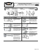
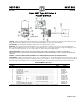
*WHERE SEPARATE POWER SUPPLIES ARE PROVIDED, THE DISCONNECT MEANS FOR EACH MOTOR MUST BE
GROUPED TOGETHER AND PROVIDED WITH SUITABLE WARNINGS IN ACCORDANCE WITH THE NATIONAL
ELECTRICAL CODE AND ALL OTHER APPLICABLE CODES AND STANDARDS.
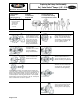
CLASS 9038 MECHANICAL ALTERNATOR – WIRING DIAGRAMS*
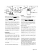
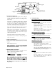
EXPLANATION OF FLOAT TRAVEL AND POSITION
NORMAL OPERATION: Switches will cut in and out at the high point and
low point of distance A plus B, given in the tables. Under normal conditions,
as long as one pump alone is able to handle the incoming water, the pumps
will alternate at this distance. With the water level continuing to rise, the
second switch will cut in and start the second pump when the float reaches
the top of distance D. Both pumps will continue to run until the float returns
to the low point of distance D plus C, where one pump will cut out. The
other pump will continue until the float reaches the low point of distance B.
Type CG
65013-013-91A Supersedes 9038-893
Dated March, 1988
JUNE 1988