
User guide


Page 3 of 10
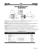
• Selection
Be sure to select a pump that is big enough for the job.
Select a capacity rating adequate for the maximum amount
of condensate expected under the most severe conditions.
Remember that pressure rating
must be sufficient to operate
against maximum boiler pressure, plus
lift and friction in
piping between the pump and the boiler.
Sterlco
®
pumps have rated capacities of three times the
maximum flow of condensate for the specified amount of
radiation; in other words, when the heating system is
running at maximum capacity, the pump should not be
operating more than one-third of the time. This is a
minimum factor of safety. If heavy overloads are possible,
an oversized condensate pump should be selected.
For most applications, where the pump is above floor level
and in a reasonably dry location, Sterlco
®
4100, 4200 and
4300 series pumps (for smaller jobs) and 3500 series
pumps (for larger capacities and higher pressures) provide a
wide range of selection. When the return is below floor
level, 3700 series pumps with epoxy-coated steel tanks are
recommended.
• Heating Plant
Before a condensate pump can operate satisfactorily, the
heating plant itself must be in good order.
The most important point to remember is that all heating
units and return lines must be equipped with properly
selected Sterlco
®
traps in good working order. With
improper or malfunctioning steam traps, steam or water
above 190°F may return to the condensate pump. For best
operation, condensate should be 160°F or less. Although
Sterlco
®
pumps can operate at higher temperatures, we
cannot guarantee full capacity or satisfactory operation if
condensate is allowed to go above 190°F.
For unusually hot condensate, a specially designed unit
may be required.
It is equally important to provide Sterlco® strainers on all
lines, to keep scale and dirt out of the tank and pumps.
• Location
Locate the pump as close to the boiler as practical. A
more powerful pump will be needed if it must be far away
from the boiler or below the boiler.
Locate the pump above floor if possible, in a position
where it will be clean
, dry, and easily accessible.
Locate the tank inlet below the lowest point of return lines.
If the pump must be below floor level, use a 3700 series
unit with epoxy-coated steel tank and take all possible
precautions to keep the motor and electrical equipment dry.
Set the pump on a substantial, level foundation – preferably
off the floor, on a raised concrete base.
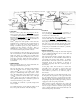
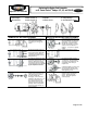
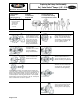
• Pipe Connections
Typical condensate pump hookups are shown in the diagrams.
No two individual installations will be exactly alike, but
certain essentials apply to all:
The condensate inlet should be equipped with a strainer to
keep scale and dirt out of the tank, unless all return lines are
exceptionally well protected with strainers. In addition,
there should be some means (such as the isolation valve
arrangement shown in the diagrams) of disposing of
condensate temporarily when the condensate pump is
disconnected.
At the pump outlet, there should be a check valve
(reasonably close to the pump) to prevent water from
flowing back out of the boiler. In addition, an isolation
valve should be provided for use when the pump is
disconnected.
The vent opening at the top of the tank must be left open to
the atmosphere. Good practice is to run a pipe from the vent
up to the ceiling, then down to a point near the floor drain.
This keeps dirt out of the tank and helps keep the motor dry.
For priming the pump when starting up or testing, a union or
a plugged tee at the vent opening is desirable.
Many variations in piping arrangements are possible; and
local codes vary widely. For example, in some cities there
must be a bypass around the condensate pump with gate
valves, so that the return line can be connected directly to the
boiler when the pump is disconnected.
3500 Series 3700 Series
Floor Line
Motor & Pump
Isolation
Valve
Check Valve
Discharge Line
to Boiler
Isolation
Valve
Return Cond.
Line
Float Switch
Isolation
Valve
Strainer
Cond. By-Pass Clean-
Out Pipe to Floor Drain
Vent: Pipe Line up to Ceiling then to Floor Drain
Vent: Pipe Line up to Ceiling
then to Floor Drain
Priming Plug
Float Switch
Floor Line
Motor & Pump
Check Valve
Isolation
Valve
Return Cond. Line
Discharge Line
to Boile
r