AccuMeter TM Continuous Loss-in-Weight Feeding Systems with Allen-Bradley COMPACTLOGIXTM Control System Part Number: Bulletin Number: Effective: 882.01181.00 BF1-625 3-5-2009 Since we are committed to a continuing program of product improvement, specifications, appearance, and dimensions described in this manual are subject to change without notice. DCN No. ____________ © Copyright 2009 All rights reserved.
Shipping Information Unpacking and Inspection You should inspect your equipment for possible shipping damage. Thoroughly check the equipment for any damage that might have occurred in transit, such as broken or loose wiring and components, loose hardware and mounting screws, etc. In the Event of Shipping Damage According to the contract terms and conditions of the Carrier, the responsibility of the Shipper ends at the time and place of shipment.
Credit Returns Prior to the return of any material, authorization must be given by the manufacturer. A RMA number will be assigned for the equipment to be returned. Reason for requesting the return must be given. ALL returned material purchased from the manufacturer returned is subject to 15% ($75.00 minimum) restocking charge. ALL returns are to be shipped prepaid. The invoice number and date or purchase order number and date must be supplied.
Table of Contents CHAPTER 1: SAFETY ..................................................................... 7 1-1 1-2 1-3 How to Use This Manual ............................................................................................. 7 Safety Symbols Used in this Manual ...........................................................................8 Warnings and Precautions .................................................................................... …..9 Responsibility ..............................
CHAPTER 7: SETTING THE IP ADDRESS FOR THE ACCUMETER DISPLAY................................................................. 44 CHAPTER 8: OTHER SETTINGS FOR THE ACCUMETER DISPLAY INITIALIZATION............................................................. 48 CHAPTER 9: PROGRAMMING THE DISPLAY FROM THE FLASH CARD................................................................................. 50 CHAPTER 10: PRINTER SETUP FOR PANELVIEW PLUS CE .. 56 CHAPTER 11: CONFIGURING A NEW PLC...........................
CHAPTER 19: SECURITY ............................................................ 98 CHAPTER 20: TECHNICAL ASSISTANCE................................ 100 Parts Department ....................................................................................................100 Service Department.................................................................................................100 Sales Department....................................................................................................
Chapter 1: Safety 1-1 How to Use This Manual Use this manual as a guide and reference for installing, operating, and maintaining your Continuous Loss-in-weight Blender. The purpose is to assist you in applying efficient, proven techniques that enhance equipment productivity. This manual covers only light corrective maintenance. No other maintenance should be undertaken without first contacting a service engineer.
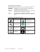
Safety Symbols Used in this Manual The following safety alert symbols are used to alert you to potential personal injury hazards. Obey all safety messages that follow these symbols to avoid possible injury or death. DANGER! DANGER indicates an imminently hazardous situation that, if not avoided, will result in death or serious injury. WARNING! WARNING indicates a potentially hazardous situation or practice that, if not avoided, could result in death or serious injury.
1-2 Warnings and Precautions Our equipment is designed to provide safe and reliable operation when installed and operated within design specifications, following pertinent local and national codes. This may include, but is not limited to OSHA, NEC, NFPA, CSA, UL, CE, SPI, and any other local, national and international regulations.
1-3 Responsibility These machines are constructed for maximum operator safety when used under standard operating conditions and when recommended instructions are followed in the maintenance and operation of the machine. All personnel engaged in the use of the machine should become familiar with its operation as described in this manual. Proper operation of the machine promotes safety for the operator and all workers in its vicinity.
Operator Responsibility The operator’s responsibility does not end with efficient production. The operator usually has the most daily contact with the equipment and intimately knows its capabilities and limitations. Plant and personnel safety is sometimes forgotten in the desire to meet incentive rates, or through a casual attitude toward machinery formed over a period of months or years. Your employer probably has established a set of safety rules in your workplace.
• Clean the blender and surrounding area DAILY, and inspect the machine for loose, missing or broken parts. • Shut off power to the blender when it is not in use. Turn the switch to the OFF position, or unplug it from the power source. Maintenance Responsibility Proper maintenance is essential to safety. If you are a maintenance worker, you must make safety a priority to effectively repair and maintain equipment.
Chapter 2: Functional Description 2-1 Models Covered in This Manual This manual provides operation, installation, and maintenance instructions for continuous lossin-weight blenders of various blending rates and specifications. See Figure 1 below for a list of available models and specifications. Figure 1: Models Covered by this Manual (√ - Denotes Availability) Model Blending Capability 2 components 3 components 4 components 6components 8 components Maximum blending rate in lbs./hr .(kgs.
2-3 Typical Features & Components Mechanical Features • Adjusts individual feeders to match learned extruder rate at the ratio required. • Upper material re-fill hoppers with conical, butterfly of slide gate style re-fill valves and dust boots, depending on model. • Individual ingredient weigh hoppers. • Cast aluminum feeder housings with drains on pellet feeders. • Cast or fabricated stainless steel feeder bodies on powder feeders.
Control System Features • Allen-Bradley CompactLogixTM control system with: • Allen-Bradley CompactLogixTM programmable controller • Allen-Bradley PanelView Plus CE color touch screen o Easy menu-driven format o USB printer port o Recipe storage book o Inventory and material usage information o Ethernet communications module OR • C2 control system with: • Oberon operating system • Color touch screen o Easy menu-driven format o Serial printer port o Recipe storage book o Inventory and materi
Blender System Component Description This section describes the various components of the continuous blending system.
level alarm to be wired into a separate controller. These would not be present on a standard blender. The hoppers may be equipped with a polycarbonate sight glass. This is mounted in the upper cone section of the hopper. This is useful for a quick reference of the material level in each hopper. The supply/re-fill hoppers should be vented to the atmosphere through the louver located on the lid of each hopper.
Ingredient Metering/Transport Auger Assemblies Each metering auger assembly consists of a: • Cast aluminum motor mount • Cast aluminum feeder body • Aluminum feeder tube • Gearbox • Inverter-duty AC drive motor • Machined metering auger The metering auger assembly accurately meters the material from the ingredient weigh hopper at the calculated rate.
Lower Mass Flow Weigh Hopper Assembly The lower mass flow weigh hopper, otherwise known as the weighed common hopper, is used to determine the actual processing rate of the processing machine so that the blender can be slaved in to run at the learned rate. The hopper is constructed of spun aluminum and is of the mass flow type (See the glossary in the Appendix).
PLC Control Panel The PLC control panel may be mounted on the side of the blender frame, or remote mounted near the blender. It uses an Allen-Bradley CompactLogix programmable controller with standard 24 vdc input output cards. This design provides excellent blender performance along with easily replaceable off-the-shelf parts in case of any electronic component failure. Touch Screen Interface The PanelView Plus CE color touch screen display is mounted by default in the PLC control panel.
2-4 Options The following is a list of options, which your blender may have been equipped with: • Powder feeders • Digital dosing feeders • Mezzanine stand with slide gate and 4” tube stub. • Supply hopper lids for non-ACS supplied vacuum receivers & loaders. • Agitated, straight wall regrind supply & weigh hoppers for regrind material. • Compressed air loader for low percentage additives.
2-5 Safety Devices and Interlocks This section includes information on safety devices and procedures that are inherent to the continuous loss-in-weight blender. This manual is not intended to supersede or alter safety standards established by the user of this equipment. Instead, the material contained in this section is recommended to supplement these procedures in order to provide a safer working environment.
Some safety devices disconnect electrical energy from a circuit. The safety devices that are used on the continuous loss-in-weight blenders are primarily concerned with electrical power disconnection and the disabling of moving parts that may need to be accessed during the normal operation of the machine. Some of the safety devices utilize a manual activator. This is the method of initiating the safety lock out. This may be in the form of a plug, disconnect plug, lever or a handle.
Chapter 3: Installation 3-1 Uncrating the Equipment Continuous loss-in-weight blenders are shipped bolted on a skid, enclosed in plastic wrap, and contained in a wood crate. 1. Remove the crate from around blender. 2. Secure strap of proper lifting capacity to the lifting lugs installed in the holes provided. Caution! Use approved safety straps or chains to lift the blender from the eyebolts on the top plate (See figure 6 below for eyebolt positioning).
Site Requirements This section describes site requirements in detail. These requirements are broken down into mechanical mounting, electrical connections and pneumatic connections. Since the continuous loss-in-weight blender is available in several different mounting arrangements, it is necessary for the reader to become familiar with the different arrangements. Mounting Configuration The continuous loss-in-weight blender is available in (3) three basic mounting arrangements.
Note: Never weld on the blender’s frame, machine or mezzanine without first removing the control panel and verifying that the blender’s power is disconnected. Mezzanine Mount In a mezzanine mount application, review the following items before installation begins. First, verify the blender mounting locations match the mezzanine supports. Verify that the mezzanine is capable of supporting the blender with a full load of material and loading equipment installed.
Note: Ensure that the feed tube angle is steep enough (60 degrees is recommended). Note: Some mezzanine mount applications will require the blending system’s lower mass flow hopper be mounted on the extruder throat. The metering section will be mounted on a small stand on the mezzanine directly above the extruder with a 4” tube stub for gravity metered flow. Note: This arrangement will be similar to the floor mounted configuration, discussed in the following section, less the blower assembly.
3-3 Electrical Installation The continuous loss-in-weight blending system is designed to operate on 115 volt or 220 volt, single phase, 50 or 60 hertz AC power. The power requirements will vary with the blender’s size and throughput rating. For exact current requirements, check the blender serial number tag, located on the blender motor control panel. As an added option, the manufacturer may provide a voltage transformer for special supply voltage.
3-4 Pneumatic Installation The blending system utilizes air pneumatics to perform the re-fill function on the ingredient weigh hoppers. The manufacturer provides all pneumatic plumbing to a single ¼” standard pipe thread fitting. The blender requires a maximum of 60 PSI of compressed air. It is the customer’s responsibility to ensure that the air is CLEAN, DRY & LUBRICATED. Any component failures due to airborne contaminants will not be subject to warranty consideration.
3-5 Overall Installation (Summary) This installation procedure should be used as a general guideline for the proper installation steps required to install the continuous loss-in-weight blending system. 1. Visually inspect the extruder or blender mounting location for obstructions. 2. Remove the material supply hopper on the extruder flange. 3. Carefully lift blender into place above the mounting flange on the extruder and fasten the blender to the flange using the extruder flange bolts.
3-6 Set-up This section will discuss the mechanical setup and control system setup of the continuous lossin-weight blending system. After reading this section, you should be familiar with the mechanical setup and the electronic control setup of the blending system. Load Cell Adjustment The mechanical setup of the continuous loss-in-weight blending system involves the adjustment of the weigh hopper load cells (Please refer to the figure below).
Final Connections 1. Connect the blender to the appropriate power source. 2. Connect the compressed air piping, ensuring that a 5-micron air filter is installed, along with the proper water trap, and lubrication unit, if required. Verify that 60 psi (4.14 bar) of clean, dry compressed air is supplied to the blender.
Chapter 4: Making programming chips This chapter should be used only if you have a new PLC and/or display that has not been programmed from the factory (new from Allen Bradley). You will need to have acquired a set of programming chips from ACS service or engineering before proceeding. You may also inquire to have the image for these chips emailed to you. This will allow you to purchase chips and a compact flash burner locally.
Chapter 5: Programming a New PLCs IP address The Compact Logix CPU has a built in Ethernet port that is assigned an IP address by running a utility from Allen Bradley called “BootP/DHCP Server”. This is available for a free download from www.ab.com. You will need to sign up for a free account and will need to search downloads to get it. This can be downloaded from Allen Bradley or provided by ACS upon request. 1. Go to http://www.software.rockwell.com/support/download/ 2.
How to Use the BOOTP-DHCP Server to Set the IP Address of the Compact Logix PLC You need to program the IP address of the Coexpert-Master PLC to 192.168.0.141 1. You will need to use a laptop and a cross-over cable to connect from your laptop directly to the Ethernet connector on the Compact Logix CPU. Note: Administrative Rights are needed on the computer to do these steps. Also some laptops have built in Wireless NIC or some computers have more than One NIC card.
4. Select properties of the card (the LAN card, not the Wireless card). You must disable the wireless card by right clicking on it and selecting “Disable”.
5. This will bring up the following window. The following Card is setup to use a DHCP server to get and IP address. Change it to a Static IP address. 6. Put in the IP address of 192.168.5.1 (if you are using a tying this into your plant network and are using a different IP subnet then consult your IT department) with the subnet mask of 255.255.255.0 7. 8. Click the Ok button, and then click the Close Button. The IP address is now set.
9. The first time opening it will ask you to configure the server. You need to enter the subnet mask as shown above 255.255.255.0. Then Click the OK button. 12. Now connect and reboot the Compact Logix PLC to your computer you should see BOOTP requests fill the upper screen of the Server.
13. Select one of the requests in the Request History window and select the Add to Relation List button. That will open a window which will automatically import the MAC address of the Processor. Type in 192.168.5.103 for the IP address (if you are using a tying this into your plant network and are using a different IP subnet then consult your IT department). Then click on the OK button. 14. In the Request History window the MAC Address has the IP address reported back to the server.
16. Push the Disable BOOTP-DHCP button. You should get the following Response. 17. IT IS VERY IMPORTANT TO RECEIVE THIS MESSAGE! If you don’t and you close this Server then the processor will lose its IP address upon power up. 18. If this is not successful then you will see this: 19. If the following error happens, wait one minute, click the OK button and try to disable the BOOTPDCHP again. Repeat this till action until the BOOTP-DCHP is disabled.
20. It is also important to test that it has been disabled. First clear the history by touching the “Clear History” button. Next reboot the Compact Logix PLC. Check to make sure that you do not see any request in the “History” window. If you do then repeat the disabling procedure as mentioned in prior steps. 21. After you have successfully completed all prior steps you can test the Compact Logix Ethernet port by attempting to “ping” it.
22. Now if a request ping timeout occurs after setting the IP address. Perform the following in a command Prompt. Type ipconfig /flushdns and hit enter. Then retry the ping command.
Chapter 6: Programming a New PLC Programming the PLC is done by using the PLC PROGRAM CARD compact flash card that you made in an earlier chapter. • Locate the card slot on the PLC and insert the PLC PROGRAM CARD as shown below: • Next reboot the PLC by turning the power off then on. It is HIGHLY important that you do not remove the power during this step until the RUN, IO, and OK lights are SOLID GREEN. The card contains a firmware upgrade in the case the firmware is different on the CPU you are using.
Chapter 7: Setting the IP Address for the AccuMeter Display The IP address of the AccuMeter Display is not part of the program and must be configured on a new unit by accessing the terminal settings menu from the PanelView Plus CE. By default you should set it to 192.168.5.104 unless you are tying this unit into your existing plant network (refer to your IT department for details) 1. When the PanelView Plus CE should automatically take you to the RSVIEW ME Station setup.
3. Scroll down and hit enter at “Network and Communications” 4. Scroll to “Network Connections” and hit the “enter” arrow.
5. Scroll to “Network Adapters” 6.
7. Touch “IP Address” and enter in “192.168.5.104” 8. Hit “enter”, “ok”, then “ok”, then “close”, then “close”, then “close”, then “close”, then turn the power off and then back on and allow it to reboot before proceeding.
Chapter 8: Other Settings for the AccuMeter Display Initialization At this point you should have just rebooted the display. If you are using this section of the manual on a working unit then you will need to access the DISPLAY CONFIGURATION PAGE by logging in as a SUPERVISOR and then touch the ACS icon, then Display Configuration, then PANELVIEW PLUS CE CONFIGURATION to get here. 1. Touch “Terminal Settings” 2.
3. From this page go under Cursor and disable the Cursor. Then go under Screen Saver and disable the screen saver. Using a screen saver is a customer option and will increase the life of the display dramatically. When finished hit CLOSE to go back to the Terminal Settings page. 4. From the terminal settings page you can access the Time/Date/Regional Settings page to setup these items. They are used for alarm date/time info.
Chapter 9: Programming the display from the Flash Card. First insert the DISPLAY PROGRAM CARD into the slot on the back of the display as shown below: AccuMeter Controller Chapter 9: Programming the display from the Flash Card.
Touch “Load Application” Touch Source until it shows “External Storage 1” and click “Load” AccuMeter Controller Chapter 9: Programming the display from the Flash Card.
You will be prompted with the following screen. You need to click “yes”. If you are tying this unit into your existing plant network then you must still click yes initially, then you must repeat this loading process and select “no” the second time. This will allow you to go under the RS View Communications setup and program the PLC’s device shortcut according to your scheme. Refer to ACS engineering for more details on this procedure.
2. Scroll to “Startup Options” and hit enter 3. Hit enter again here AccuMeter Controller Chapter 9: Programming the display from the Flash Card.
4. Select “Run Current Application”. If this is disabled you have not loaded the display program yet and need to review the previous steps AccuMeter Controller Chapter 9: Programming the display from the Flash Card.
5. Click OK when you see the screen below. This step is what tells the display to always load the program from the chip. THE CHIP WILL REMAIN IN THE DISPLAY ALWAYS. Keep touching “OK” until you are back to the original page.
Chapter 10: Printer setup for PanelView Plus CE From the VersaView config screen touch Terminal Settings AccuMeter Controller Chapter 10: Printer setup for PanelView Plus CE 56
Then scroll to “Print Setup” and hit “enter” Scroll to Display Print Setup and hit enter AccuMeter Controller Chapter 10: Printer setup for PanelView Plus CE 57
Setup the printer from this page Advanced Settings Shown Below FOR A COMPLETE LIST OF COMPATIBLE PRINTERS REFER TO YOUR LOCAL ALLEN BRADLEY DISTRIBUTOR OR THE ALLEN BRADLEY WEBSITE AccuMeter Controller Chapter 10: Printer setup for PanelView Plus CE 58
Chapter 11: Configuring a new PLC This chapter should be used only if you are either upgrading a blender’s controls from a C2, Covis, or OL controller. You can also use this chapter as a guide to configuring a new PLC. This chapter does not cover the actual programming of a blank PLC (that is covered in Chapter 6). This chapter details every parameter for an AccuMeter system, but assumes that both the Display and PLC are programmed and communicating.
Step 2: Enabling the I/O cards of the PLC • By default in the program all of the I/O cards are disabled. This allows you to use the same program on multiple different platforms that all use different cards. • After logging in as the SUPERVISOR touch the ACS icon from the main recipe page to bring up the SETUP DIRECTORY. • Once you are in the SETUP DIRECTORY touch the ACS icon again to enter in the ACS ENGINEERING ONLY DIRECTORY.
• From the ACS ENGINEERING ONLY DIRECTORY touch ENABLE I/O SLOTS • Open the PLC panel and observe which cards are present. Set each slot that is present to “ENABLED” by touching the slot’s box. Be sure to use caution while doing this. If you make a mistake then the PLC will fault and you will need to reboot the PLC and start this step over. Unlike earlier versions you will not loose all of the other settings when this happens.
Step 3: Mechanical Options (Accessed from ACS ENGINEERING ONLY DIRECTORY) • Assign each feeder to the appropriate blender by touching here. • Set the maximum number of feeders by touching the box. • Setting INTERLOCKS to Normally Closed allows the feeder to run when the signal is LOW. Setting this to Normally Open allows the feeder to run when the signal is HIGH. • When done touch “DONE” twice to get back to the SETUP DIRECTORY page to continue this chapter.
Step 4: Items on the SETUP DIRECTORY • Use the UNITS page to change from Metric to Imperial. If this is changed then you will need to reconfigure all weight settings, recalibrate all loadcells, and recalibrate all feeders. • You can also modify the password for the current level that you are logged into by going under PASSWORDS and then touch “Change Password”. • Access the DISPLAY CONFIGURATION page to observe the software version in both the display and the PLC.
Step 5: Feeder Configuration Settings Once you have configured the SETUP and ACS ENGINEERING ONLY settings then you must configure each feeder appropriately based on the physical equipment. Start by touching the icon for the feeder from the main recipe page. This will bring up the FEEDER POPUP page that will allow you to configure all of the feeders settings.
FEEDER SETUP Tab • DISPLAYED NAME for the feeder as it appears throughout the controller. The electrical documentation and alarm log refer to them as FEEDER A-L regardless of the label here. • Change the GRAPHIC that is used to represent the hopper by touching the small graphic icon. • Modify the HOPPER SIZE. This is the value that the system will fill the hopper to during refill.
FEEDER SETUP Tab (continued) • MIN/MAX SPEED% are the limits at which the controller allow the drives to run and are used to determine the MIN/MAX blend rate for any given recipe. It is important that these limitations be set appropriately for the given motor/drive technology. Refer to service before changing • REFILL SETTLE TIME (SECONDS) is the amount of time that the controller will weight for the hopper to settle after a refill before looking at the weight.
ALARM SETUP Tab • NO FLOW ALARM ENABLED/DISABLED. This alarm occurs if the feeder is running and the system does not detect weight loss. This could happen if there was a material bridge in the hopper. RUN on alarm means that you want the blender to continue running regardless of this condition. STOP on alarm means that you want the blender to shutdown if this condition is detected. • NO FLOW TIME (SECONDS). This is the sample window that is used in determining if a no flow condition occurs.
CALIBRATE SCALE Tab • CALIBRATION WEIGHT VALUE. This is the weight that was used during the last scale calibration. This can be changed just by entering in a new value. • ZERO BITS. This is the stored value in bits that was recorded when the hopper was empty during the last scale calibration. • CAL BITS. This is the stored value in bits that was recorded when the calibration weight was hung on the hopper during the last calibration. • SET “Zero bits”.
CALIBRATE FEEDER Tab • MOTOR SPEED FOR CALIBRATION. This is the speed at which the motor will be ran during the feeder calibration. Ideally it should be set at a value close to what the motor will be running during blender operation. In some cases this is too slow and causes the feed calibration to take significant time. • DISPENSE WEIGHT FOR CALIBRATION. This is the amount of weight that the system will dispense during the feeder calibration.
FIFO SETUP Tab • SAMPLE SIZE IN %. This is the percent of hopper that is sampled for the data point entered into the FIFO. Making this number smaller makes the system respond more quickly. Making this number too small will induce unwanted error in the algorithm. Making this number larger will delay the samples and dampen the controller. • NUMBER OF POINTS IN FIFO. This is the number of samples that will be analyzed by the FIFO algorithm to determine if the feeder’s weight loss is steady.
FIFO DATA Tab • PRIMARY FIFO. This is the primary FIFO that contains up to 20 slots that is used in the analysis of the weight loss. This FIFO will be filled to the NUMBER OF POINTS IN FIFO (FIFO Setup Tab). Once this happens the range of these values is used to calculate a %Dif that is displayed below the FIFO. If the %Dif is below the ALLOWABLE % DIFFERENCE FOR STEADY (FIFO Setup Tab) then the FIFO STEADY message will be shown below the FIFO. • SECONDARY FIFO.
TREND DATA Tab • NOTE ON TREND DATA. This tab is used to monitor the measured hopper weight. You must keep this tab FEEDER POPUP window up to log data. It is useful to see if something is intermittently interfering with the loadcell circuit. At this time it is not a long term data acquisition tool, but only used for troubleshooting.
Step 6: Massflow Hopper Configuration Settings Once you have configured the SETUP and ACS ENGINEERING ONLY settings then you must configure each feeder appropriately based on the physical equipment. Start by touching the icon for the hopper from the main recipe page. This will bring up the MASSFLOW POPUP page that will allow you to configure all of the massflow settings.
HOPPER SETUP Tab • DISPLAYED NAME. This is displayed above the blender on the main recipe page and on the top of every “pop-up” page to tell you which piece of equipment you are on. • MASS FLOW HOPPER ENABLED/DISABLED. Set the to enabled if you have a weighed mass flow hopper. If you are either using a central non-weighed collection hopper with 2 prox switches (high/low) or are starve feeding a process without any collection hopper then DISABLE this.
ALARM PAGE Tab • NO FLOW ALARM ENABLED/DISABLED. This alarm is generated if the blender is running and the extruder is not taking material away. This could happen if a bridge forms directly over the feed throat. • NO FLOW TIME (SECONDS). This is the sample time that is used to determine if a NO FLOW condition exist. Entering “0” will disable the alarm. • NO FLOW BITS.
CALIBRATE SCALE Tab • CALIBRATION WEIGHT VALUE. This is the weight that was used during the last scale calibration. This can be changed just by entering in a new value. • ZERO BITS. This is the stored value in bits that was recorded when the hopper was empty during the last scale calibration. • CAL BITS. This is the stored value in bits that was recorded when the calibration weight was hung on the hopper during the last calibration. • SET “Zero bits”.
PID SETUP Tab • PID UPDATE TIME. This is the rate at which the PID will make corrections to the target blend rate to attempt to maintain the weight at the median point between the RELOAD % (Hopper Setup Tab) and the HOPPER SIZE value (Hopper Setup Tab). Setting this value smaller will allow the blender to react quicker to changes in the bulk density of the material. Setting it too low will cause the control to become under damped and out of control.
FIFO SETUP Tab • SAMPLE TIME ONCE IN STEADY WINDOW. Once the blender achieves “In Steady Window” then it begins to calculate the extrusion process rate at this sample interval. Setting this value too fast can add error to the process rate data. Default is 10 seconds. • NUMBER OF POINTS IN FIFO. Number of samples based on above interval that are analyzed by the FIFO algorithm. Increasing this value can smooth out the result. • ALLOWABLE % DIFFERENCE FOR STEADY.
FIFO DATA Tab • PRIMARY FIFO. This is the primary FIFO that contains up to 20 slots that is used in the analysis of the weight loss. This FIFO will be filled to the NUMBER OF POINTS IN FIFO (FIFO Setup Tab). Once this happens the range of these values is used to calculate a %Dif that is displayed below the FIFO. If the %Dif is below the ALLOWABLE % DIFFERENCE FOR STEADY (FIFO Setup Tab) then the FIFO STEADY message will be shown below the FIFO. • SECONDARY FIFO.
TREND DATA Tab • NOTE ON TREND DATA. This chart allows you to visually see how the PID is reacting to the changes in the mass flow weight. You must leave the pop-up visible in order to track it and is not intended to be a long term data acquisition chart. The Green is the Blender Target Rate while the Blue is the Mass Flow Weight. This page is only used in the initial setup of the blender and for troubleshooting.
Chapter 12: Quick Startup and Calibration This section describes the quick startup for a blender and controller that has been factory programmed, mounted, and configured on a new unit. Do not use this section if you are upgrading to the AccuMeter Control Logix platform from either a C2, Covis, or OL controller. For retrofits refer to the Detailed Configuration Parameters chapter. Do not use this section if you are starting with a PLC or Display that has not yet been programmed.
Step 2: Login to the Controller as the “OPERATOR” • From the main page touch “LOGIN” to bring up the login page • From the main page touch “LOGIN” to bring up the login page • Touch “User” and enter “OPERATOR” and hit enter. • Touch “Password” and enter “5413” and hit enter • Touch the return arrow to complete the login process. You will not receive notification for success or failure. • Be sure that when you are finished calibrating the blender that you touch the “LOGOUT” button.
Step 3: Calibrate each loadcell • After logging in touch the icon for the feeder. • Touch the “Calibrate Scale” tab. • Locate the calibration weight listed here. • Empty hopper and then touch “SET Zero Bits”. • Hang calibration weight from hopper and touch “SET Cal Bits”. • Repeat this for all hoppers that have loadcells.
Step 4: Calibrate each feeders • It is necessary to perform a feeder calibration with material to initialize the feed algorithm. The controller will automatically determine this, but by doing so you decrease the amount of learn time required. It is easy to perform and is recommended that every time you switch resins with significantly different weights and flow values that you run a feeder calibration.
Step 5a: Enter the Recipe and Start the blender (skip to 5b if you are running all feeders offline and not running them together as a blender) AccuMeter Controller • Verify that all materials have been loaded into each hopper • Touch the blue recipe percent box for each feeder and enter in the desired percentage. Remember that the total must add to 100%. If the total is not 100% then you will be notified by a Red message.
AccuMeter Controller • After entering in a recipe that adds to 100 and is acceptable by the blender you will be given an “Accept Recipe” button. Touching this button will enter in the new recipe and will make the button disappear. • If the blender is either used as a starve feeder or it does not have a central weigh hopper then you will also need to enter in the target total blend rate here. • To make the blender start running touch the “on/off” switch.
Step 5b: Configuring a system to run with all feeders offline for individual control (skip this section if you are using the feeders together as a blender) AccuMeter Controller • You will first need to enter in “0” values into every feeder’s blue recipe box.
Chapter 13: The Recipe The AccuMeter blender controller allows a user to specify a recipe much similar to a cooking recipe that tells the system how much of each material to blend. Typically the recipe is in percent of overall blend and must add to 100. In some configurations the blender may be broke down into individual feeders that are not linked by a recipe, but controlled by the same system. In this case the user would instruct the system on how many lbs/hr or kgs/hr to run out of the feeder.
RECIPE ERROR MESSAGES: Recipe total not 100% Recipe cannot run with current feeders RECIPE CANNOT RUN WITH CURRENT FEEDERS: This message means that the current recipe cannot be ran at any rate due to the percent entered and the current feeder calibrations for each feeder. The feeder calibration is related to the auger size, gearbox ratio, and the material’s bulk density. This scenario is difficult for most to understand and can best be explained using an example. Take for example you only have 2 feeders.
typically used for a color component. It can run between 1-100 lbs/hr. Feeder 2 is a large auger that is typically used for virgin. It can run between 200-2000 lbs/hr. You can clearly see that if you entered in a recipe of 50% and 50% that there would not be any speed at which the two feeders could equal each other to produce a 50/50 blend. The fastest the small auger could run is 100 lbs/hr. The slowest the large auger could run is 200 lbs/hr. At these limits you could only achieve a 33%/67% blend.
Chapter 14: The Mass Flow Data Page This page can be reached by touching the icon for the mass flow hopper from the recipe page. Indication that mass flow weight is in the steady window Blending Range based on recipe and feeder calibrations Weight at which all feeders will be shut off. Steady Window showing MEDIAN point Weight at which all feeders will run at the maximum blending rate Access to active alarms page Target/Actual blender throuhgput AccuMeter Controller Inventory of entire blender.
A typical pop-up page for fixed rate units that use a non-weighed central collection hopper. These orange prox graphics will show a RED dot when the system sees material. This should correspond with the light on the real prox Without a weighed mass flow hopper the operator must set the blend rate manually. This is also useful when starve feeding as you can specify precisely the rate you wish to blend at.
Chapter 15: The Feeder Data Page Each feeder has a pop-up page that can be accessed by touching the icon for the hopper from the recipe page. Below details what is shown. Manual reload control. Red Circle means reload is shut Graphical representation of hopper weight between RELOAD (NOT EMPTY) and FULL. Visible when alarms are active. Touch to access alarm page Current weight of material in hopper Hopper size and reload weight Manually entered feeder speed for cleanout or volumetric running.
Chapter 16: The Inventory Page This page is used to record, print, and clear the accumulated inventory for each feeder as well as for the overall total for the blender. You must first log in before you can clear the inventory. Not doing so will not give you an error message, but simply won’t clear the inventory. After you log in and press “Clear Inventory you will be prompted with a verification page before the inventories are actually cleared.
Chapter 17: Maintenance 5-1 Preventative Maintenance Schedule The mechanical design of the blender requires little maintenance. The only moving parts are the refill valves, optional regrind agitators, metering augers, and optional discharge slide gates. The checklist below contains a list of items which should be inspected and/or replaced to keep your blender operating at peak efficiency. Perform each inspection at the regular intervals listed below.
Chapter 18: Spare Parts and Specifications Typical OL Blender Parts List # 2 3 4 5 DESCRIPTION Lid (0.2 to 1.6 cu. ft. vacuum receivers) Lid (3.0 and 6.0 cu. ft. vacuum receivers) 1/8” NPT fitting 1/4” NPT fitting Bulkhead Brass elbow 6 24V DC Solenoid 7 8 Dump cone Air cylinder 1 015 08223-1 N/A 060 08278A N/A 35085K and 35086K 35154 and 35155 35146 35118 100 08412-1 A0770325 33128 15370 33126 15237 33073 33011G Weigh Hopper Parts List Analog Load cells Digital Load cells 7 kgs. 10 kgs.
Specifications The following design information is provided for your reference: 1. 2. 3. 4. 5. 6. 7. 8. 9. 10. 11. 12. 13. 14. 15. 16. 17. 18. 19. 20. 21. 22. 23. 24. 25. 26. No modifications are allowed to this equipment that could alter the CE compliance Ambient temperature: 0-55 C (32-131 F) – Maximum Humidity range: 5-95% without condensation Altitude: 2000 m (6561 ft) without derating Environment: Clean, dust-free and non-explosive Radiation: None Vibration: Minimal, i.e.
Chapter 19: Security Note: Personnel not extremely familiar with this blender controller should not use this section of the manual, or program can be compromised! Note: Hidden, programmable features and hidden menu pages should not be made available to floor operators. These pages also include the Service Supervisor Information addendum located in this section.
Security Basics The AccuMeter controller is setup with 3 levels of access: 1. Entry Level (no login required). This level always has access to: • Change Recipe • Change Target Blend Rate (for fixed rate units) • Start/Stop feeders or blender • View Alarms • View Inventory 2. OPERATOR LEVEL.
Chapter 20: Technical Assistance Parts Department Call toll-free 7 am–5 pm CST [ 800] 423-3183 or call [262] 641-8610 or Fax [262] 641-8653 The ACS Customer Service Group will provide your company with genuine OEM quality parts manufactured to engineering design specifications, which will maximize your equipment’s performance and efficiency. To assist in expediting your phone or fax order, please have the model and serial number of your unit when you contact us.