Sterling, Inc BP2400 SERIES GRANULATORS OPERATION AND MAINTENANCE MANUAL COPYRIGHT 2009 July 29, 2009 ALL RIGHTS RESERVED Sterling, Inc Size Reduction Division 2900 South 160th Street New Berlin, WI 53151 USA PART NO. D48160s Bulletin No.
Sterling, Inc. 2900 South 160th Street New Berlin, WI 53151 Tel: 1-262-641-8600 Fax: 1-262-641-8653 Parts and Service 1-800-229-2919 MACHINE DATA MODEL ___________________________________________________________ SERIAL NUMBER _____________________________________________________ CUMBERLAND CUSTOMER ORDER NUMBER___________________________________ REFER TO THIS SHEET WHEN ORDERING PARTS.
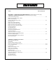
TABLE OF CONTENTS TOPIC: SECTION/PAGE Factory address. ……………………………………………………………….………2 INTRODUCTION What is a granulator?….………………………….………………………….….…11 A granulator is…. The granulating of plastics… Size of the granulate… The disposal of plastic granulate… Section 1 – SAFETY Safety symbols and plates……………………………………………………………………1-1 Learn machine safety Safety alert symbol Understand the signal words Follow safety instructions…………………………..………………………………………..
TABLE OF CONTENTS TOPIC SECTION/PAGE SECTION 2 – MACHINE PARTS AND CONTROLS…………………………………….…2-1 BP-Series granulators left front quarter view BP-Series granulators, right front quarter view..…………………………………………………….….2-2 BP-Series granulators, machine open front view BP-Series granulators, left rear quarter view …………………………..………………………………2-3 BP-Series granulators, right rear quarter view SECTION 3 INSTALLATIONS Overview…………………………………………………………………………………………….…..
TABLE OF CONTENTS TOPIC SECTION/PAGE SECTION 4 – SETTINGS AND ADJUSTMENTS (Continued from previous page) Adjusting or replacing the bed knives (Continued from previous page) Loosen the mounting screws……………………………………………………………………………..4-4 Remove the first knife clamp or shield Remove the bed knives Clean the knife mounting surfaces……………………………………………………………………….
TABLE OF CONTENTS TOPIC SECTION/PAGE SECTION 4 – SETTINGS AND ADJUSTMENTS (continued from previous page) Adjusting or replacing the bed knives (Continued from previous page) Set the down stroke knife shield…………………………………………………………………...4-15 Check the knife gap Tighten the screws to final torque Fasten the cutting chamber …………………………………..……………………………………4-16 Close the cutting chambers safety interlock Restart the granulator Drive belt replacement and adjustment….……………………………………………..…..
TABLE OF CONTENTS TOPIC SECTION/PAGE SECTION 4 – SETTINGS AND ADJUSTMENTS (Continued from previous page) Setting and adjusting the chamber jackscrew (Continued from the previous page) The chamber stops before it closes but the motor continues to run……………………………..…..4-26 Set and test the mounting bracket limit switch Close the cutting chamber………………………………………………………………………..….4-27 Fasten the cutting chamber Close the cutting chamber safety interlock……………………………………………………….....
TABLE OF CONTENTS TOPIC SECTION/PAGE SECTION 5 - (Continued from previous page) Normal operation……………………………………………………………………………………..5-4 Feed the machine Shut down the machine Discharge cleanout safety Cleaning the discharge transition Safely clearing the jam……………………………………………………………………….5-5 Work safely Jackscrew operation Open the cutting chamber Clear the jam……………………………………………………………………………………………..
TABLE OF CONTENTS TOPIC SECTION/PAGE SECTION - 6 – MAINTENANCE (continued) Screen replacement (Continued from previous page) Close screen cradle interlock……………………………………………………………………………6-8 Restart granulator Cutting chamber access…………………………………………………………………………….6-9 Work safely Open the cutting chamber interlock Release the cutting chamber fasteners Jackscrew operation…………………………………………………………………………………….
TABLE OF CONTENTS TOPIC SECTION/PAGE SECTION – 8 PARTS LISTS AND DRAWINGS Recommended spare parts………………………………………………………………………………… 8-1 Parts identification Sterling drawing no. A-48050 ……………………………………………………..….8-2 Overall dimensions Sterling drawing no. A-48150 ……………………………………………………......8-3 Parts identification Sterling drawing no. 348070C ………………………………………………………..8-4 Parts identification Sterling drawing no. 348185…………………………………………….…………….8-5 Parts identification Sterling drawing no. 1554-460 ……...
THANK YOU FOR PURCHASING AN STERLING BP2400 SERIES GRANULATOR. READ THIS MANUAL to learn how to operate and service your granulator safely. It covers the family of granulators called the BP2400. This series of Sterling Granulators is designed for the big jobs in reclamation of large blow-molded and thin walled, injection molded plastic parts as well as film. This revision of the manual covers the improvements made since the introduction of the BP2400 Series Machines in 1993.
INTRODUCTION WHAT IS A GRANULATOR? A GRANULATOR is a machine that is designed to size-reduce plastic materials to chips or granulate. The machine can be fed either by hand through a hopper opening in the front or automatically from a special hopper opening, which can be specially designed.
SAFETY SECTION 1-1 Safety Symbols and Plates LEARN MACHINE SAFETY Read this manual. Learn how to operate and how to use the control. DO NOT ALLOW ANYONE TO OPERATE THIS MACHINE WITHOUT PROPER INSTRUCTIONS. THIS SAFETY alert symbol MEANS ATTENTION…BE ALERT! YOUR SAFETY IS INVLOVED! This symbol appears frequently in this manual and on your machine. It is used to alert you to the possibility of personal injury or death. Follow the instructions in the safety messages identified with this symbol.
SAFETY SECTION 1-2 Safety Symbols and Plates FOLLOW THE SAFETY INSTRUCTIONS: Read all safety messages in this manual and on your machine safety plates. Follow the recommended precautions and safe operating practices. Keep safety plates in good condition. Replace missing or damaged plates.
SAFETY SECTION 1-3 Safety Symbols and Plates ROTATING MACHINERY SAFETY PLATE (One located on the machine guard on the left side of the machine, one on the screen cradle on the front panel, to the right of the machine center.) Avoid personal injury by making sure that the rotor is stopped and the power is disconnected and locked out before removing a machine guard. A motion sensor monitors the rotor and disables the jackscrew motors if there is rotor movement.
SAFETY SECTION 1-4 Safety Symbols and Plates JACKSCREW REVERSING OPERATION (Located on the jackscrew operating console) This information plate reminds you of the important procedure for reversing the direction of jackscrew operation. Be sure to pause as advised. This allows the jackscrew drive the necessary time to coast to a stop before reversing. Without this pause, the jackscrew may be severely damaged.
SAFETY SECTION 1-5 Safety Symbols and Plates SAFETY INSTRUCTION PLATE (Located on the front of the drive guard) The safety instruction plate summarizes the most important safety rules that you need to operate this machine safely. Read it carefully and observe it always to promote safe machine operation. HAZARDOUS VOLTAGE SAFETY PLATE (Located on the door of the jackscrew console) Always call for the services of a licensed electrician when you think that there is an electrical problem.
SAFETY SECTION 1-6 Safety Symbols and Plates ROTATING KNIVES SAFETY PLATE (One located on the front of the cutting chamber and one on the front of the cradle) The rotating knives are razor-sharp to the touch. Always verify that the rotor is not moving. Avoid personal injury by making sure that the rotor is stopped and the power is disconnected and locked out before opening the machine. A motion sensor monitors the rotor and disables the hydraulic cylinder/jackscrew controls if there is movement.
SAFETY SECTION 1-7 Safety Clothing & Practices (Located above the infeed opening at the front of the machine) It is recommended that hearing protection be used at all times when operating this equipment. It is mandatory that hearing protection be worn when noise exposure exceeds OSHA Standards Section 1910.95. (Located above the infeed opening at the front of the machine) Always wear proper eye protection when operating and/or servicing this equipment.
SAFETY SECTION 1-8 Safety Clothing & Practices WEAR PROTECTIVE CLOTHING Never wear neckties, dangling jewelry, loose-fitting clothing, watches, bracelets, or rings. Tie back long hair or restrain it with a hair net to ensure your safety. KEEP YOUR WORK AREA SAFE Keep your work area clean and uncluttered. Store your maintenance tools away from the granulator to prevent them from falling into the machine and causing severe internal damage to the cutting chamber.
SAFETY SECTION 1-9 Safety Clothing & Practices TURN OFF AND LOCKOUT the power per OSHA 1910.147 OR ANSI Z244.1-1982 (Lockout/Tag-out of Energy Sources). If it is not possible to lock out the power, have an electrician remove the fuses. Make sure the rotor has come to a complete stop. The hydraulic cylinders or jackscrews, which open the machine, should not operate until the rotor is completely stopped.
SAFETY SECTION 1-10 Safely Cleaning A Jam TURN OFF AND LOCKOUT the power per OSHA 1910.147 OR ANSI Z244.1-1982 (Lockout/Tag-out of Energy Sources). If it is not possible to lock out the power, have an electrician remove the fuses. Make sure the rotor has come to a complete stop. The hydraulic cylinders or jackscrews, which open the machine, should not operate until the rotor is completely stopped.
SAFETY SECTION 1-11 Safely Cleaning A Jam CLEAR THE JAM A leather mallet and block of wood of sufficient length to keep hands away from the path of the knives can be used if required. Use the block of wood to exert force on the rotor, usually in the direction opposite normal rotation. Make sure you have secure footing on a clean floor and keep your body well braced while prying on the rotor. Guard against loss of balance should the jammed condition suddenly come free.
MACHINE AND CONTROLS SECTION 2-1 BP 2400 Series Granulator -Left Front Quarter View Hold-down clamps - cutting chamber Screen cradle retainers Interlock actuator screw - cutting chamber Safety plates Feed hopper Rotor bearing housing Discharge duct (pipe not shown-optional mount to either side) Start/stop pushbuttons are located on the electrical cabinet, not shown. (The electrical cabinet is optional equipment.) 9. Cover, mounting bracket limit switch, jackscrew opening only. 1. 2. 3. 4. 5. 6. 7. 8.
MACHINE AND CONTROLS SECTION 2-2 BP 2400 Series Granulator Right Front Quarter View 1. Drive guard 2. Drive guard cover 3. Inlet vent -discharge blower 4. Safety plates 5. Interlock actuator screw screen cradle 6. Infeed flap BP 2400 Series Granulator Machine Open Front View 1. Screen 2. Rotor Knife 3. Bed knife (down stroke) 4.
MACHINE AND CONTROLS SECTION 2-3 BP 2400 Series Granulator Left Rear Quarter View I. Hydraulic cylinder/ jackscrew console 2. Hydraulic cylinder or jackscrew- cutting chamber 3. Cleanout- discharge transition 4. Discharge outlet (pipe not shown-optional mount to either side) 5. Rotor bearing housing 6. Rotor zero speed sensor 7. Upper chamber pivot arm screws BP 2400 Series Granulator Right Rear Quarter View 1. Hydraulic cylinder or jackscrew -cutting chamber 2. Machine serial number plate 3.
INSTALLATION SECTION 3-1 OVERVIEW This section deals with the procedures required to place your BP 2400 Series Granulator into service after you receive it at your plant. The following basic steps need to be accomplished.
INSTALLATION SECTION 3-2 MOVE THE GRANULATOR TO ITS WORK SITE If lifting the machine is necessary, use appropriately rated lifting equipment. Always lift the unit from beneath the base plate. The machine weights for the BP-Series Granulators are as follows: BP 2428-10000 pounds BP 2439-13000 pounds BP 2456-16000 pounds ALLOW ADEQUATE WORK SPACE Adequate clearance must be maintained so that all areas of the granulator are accessible and unobstructed for servicing, maintaining, or operating the equipment.
INSTALLATION SECTION 3-3 The hydraulic cylinders or jackscrews, which open the machine should not operate until the rotor is completely stopped. If you discover that the hydraulic cylinders or jackscrews DO operate while the rotor is still turning, immediately shut down the machine and call for maintenance to adjust it. Wear gloves to protect against injury from the rotor or bed knives.
INSTALLATION SECTION 3-4 ELECTRICAL WIRING To wire the granulator, run power (of the proper voltage) from the plant source through a lockable, fusible disconnect to the machine electrical control panel. To wire the jackscrew motors, run power (of proper voltage) from the plant source through a fusible disconnect to the machine-mounted jackscrew control panel. From the main electrical control panel, make the necessary control circuit connections to the hydraulic cylinders/jackscrew control panel.
INSTALLATION SECTION 3-5 CHECK FOR MECHANICAL INTERFERENCES TURN POWER OFF and LOCK IT OUT per OSHA 1910.147 OR ANSI Z244.1-1982 (Lockout/Tag-out of Energy Sources). Open the cutting chamber. Refer to the procedures entitled Screen Replacement and Cutting Chamber Access in Section 6. Turn the rotor slowly with gloved hands, at least one full revolution, to verify that there are no interferences between the rotor knives and bed knives and/or with the screen.
INSTALLATION SECTION 3-6 With all power to the electrical control panel disconnected and locked out, reverse any two of the three power line conductors to the machine. If there is more than one motor on the machine, and one is turning in the wrong direction, and one isn't: reverse any two of the three line conductors at the overload relay of the motor that you wish to reverse. Unlock the power and switch it on at the electrical disconnect (if necessary, replace the fuses).
INSTALLATION SECTION 3-6 With all power to the electrical control panel disconnected and locked out, reverse any two of the three power line conductors to the machine. If there is more than one motor on the machine, and one is turning in the wrong direction, and one isn't: reverse any two of the three line conductors at the overload relay of the motor that you wish to reverse. Unlock the power and switch it on at the electrical disconnect (if necessary, replace the fuses).
INSTALLATION SECTION 3-7 ALTERNATE TEST FOR THE INTERLOCK SWITCHES (Continued from previous page). After the test or repair, engage the screen cradle interlock actuator screw. If necessary, unlock and turn on the power. Push the start button to start the granulator. Retract the cutting chamber interlock actuator screw by turning it counterclockwise. Make sure that the end of the actuator screw is visible and clear of any contact. The granulator should stop.
INSTALLATION SECTION 3-8 TEST THE ZERO SPEED SENSOR {Continued from previous page) Screen Cradle Jackscrew Push the start button to start the granulator When the machine reaches full speed, push the stop button to stop the granulator. Open the screen cradle interlock using the procedure in Section 6-4 entitled Screen Replacement. Release the cradle retainers using the procedure in Section 6-9 entitled Screen Replacement.
SETTINGS AND ADJUSTMENTS SECTION 4-1 Adjusting or Replacing Bed Knives BASIC FACTS ABOUT THE KNIVES All of the rotor knives are ground in sets to equal dimensions. Mount and service them as sets. The rotor knives must be mounted tightly against the backs of the knife seats, in order to make it possible to achieve consistent knife clearances. Rotors with adjustable rotor knives require setting of the knife length prior to installation on to the rotor.
SETTINGS AND ADJUSTMENTS SECTION 4-2 Adjusting or Replacing Bed Knives (Continued from previous page) The hydraulic cylinders or jackscrews, which open the machine, should not operate until the rotor is completely stopped. If you discover that the hydraulic cylinders or jackscrews DO operate while the rotor is still turning, immediately shut down the machine and call for maintenance to adjust it. Wear gloves to protect against injury from the rotor or bed knives.
SETTINGS AND ADJUSTMENTS SECTION 4-3 Adjusting or Replacing Bed Knives The rotor knives and bed knives are very sharp wear heavy gloves to avoid injury. Use the rotor-locating pin to lock the rotor in the position that is least likely to cause injury as you work. The pin keeps the rotor from turning. If the rotor knives and the bed knives are to be removed, remove the rotor knives first (and replace them last) to reduce the chance of injury.
SETTINGS AND ADJUSTMENTS SECTION 4-4 Adjusting or Replacing Bed Knives LOOSEN THE MOUNTING SCREWS Select either the upstroke knife or the down-stroke knife for first removal. Loosen the bed knife screws with a 30 mm socket mounted on a breaker bar. These screws are tightened to a torque of 472 ft Ibs (640 Nm) so make sure you have the proper breaker bar (a four foot long (1.2 m) bar with a 3/4 inch (19 mm) drive is suggested). Make sure you have solid footing while you apply the breaking force.
SETTINGS AND ADJUSTMENTS SECTION 4-5 Adjusting or Replacing Bed Knives CLEAN THE KNIFE MOUNTING SURFACES Clean the knife mounting surfaces with a stone or other non-marring tool and wipe them with a clean cloth. Make sure they are free of all material, dust, and dirt. DO NOT REPLACE THE MOUNTING SCREWS WITH ANY TYPE OF SCREW OTHER THAN THAT SPECIFIED BY CUMBERLAND. Substitution of improper screws could lead to premature failure, equipment damage, and serious injury to personnel.
SETTINGS AND ADJUSTMENTS SECTION 4-6 Adjusting or Replacing Bed Knives REPLACE THE DOWNSTROKE BED KNIFE Install the down-stroke bed knife (located on the near side of the rotor) making sure to install it with the knifeedge on the upper side. Engage the captive screws in the slots on the near side of the knife bed and lower the knife onto the knife bed. Repeat these steps for the second half of the down-stroke knife.
SETTINGS AND ADJUSTMENTS SECTION 4-7 Adjusting or Replacing Bed Knives MEASURE THE KNIFE GAP If you are changing the rotor knives, do that now, otherwise, continue with this procedure. Use brass shim stock to set the knife gap to the cutting clearance of 0.006 in. to 0.008 in. (0.15 mm to 0.20 mm). Remove the rotor-locating pin. Rotate the rotor backward, by hand, and measure the gap between it and the bed knife at the point of shear.
SETTINGS AND ADJUSTMENTS SECTION 4-8 Adjusting or Replacing Bed Knives TIGHTEN THE SCREWS TO FINAL TORQUE When the knife gap is adjusted to the proper dimension, tighten the mounting screws to a torque of 472 ft lbs (640 Nm). For safety, make sure that you have solid footing when you apply this final torque. Recheck the gap after tightening the screws to the final torque. Make sure that both halves of the bed knife are adjusted.
SETTINGS AND ADJUSTMENTS SECTION 4-9 Adjusting or Replacing Bed Knives FASTEN THE CUTTING CHAMBER Raise the hold-down clamps to their upright positions Turn the knobs clockwise until they are tight against the chamber housing. CLOSE THE CUTTING CHAMBER SAFETY INTERLOCK Engage the safety interlock by turning the actuator screw clockwise with a box wrench or a ratchet wrench Make sure the screw is fully seated against the top surface of its housing.
SETTINGS AND ADJUSTMENTS SECTION 4-10 Adjusting or Replacing Rotor Knives BASIC FACTS ABOUT THE KNIVES All of the rotor knives are ground in sets to equal dimensions. Mount and service them as sets. . The rotor knives must be mounted tightly against the backs of knife seats in order to make it possible to achieve consistent knife clearances. Rotors with adjustable rotor knives require setting of the knife length prior to installation on to the rotor.
SETTINGS AND ADJUSTMENTS SECTION 4-11 Adjusting or Replacing Rotor Knives RELEASE THE CUTTING CHAMBER FASTENERS Turn the hold-down clamps counterclockwise to loosen them. Swing the hold-down clamps toward you until they are disengaged from the cutting chamber housing. SEE SECTION 6-10 PAGE 87 FOR CUTTING CHAMBER OPENING INSTRUCTIONS.
SETTINGS AND ADJUSTMENTS SECTION 4-12 Adjusting or Replacing Rotor Knives The rotor knives and bed knives are very sharp wear heavy gloves to avoid injury. Use the rotor-locating pin to lock the rotor in the position that is least likely to cause injury as you work. The pin keeps the rotor from turning. If the rotor knives and the bed knives are to be removed, remove the rotor knives first {and replace them last) to reduce the chance of injury.
SETTINGS AND ADJUSTMENTS SECTION 4-13 Adjusting or Replacing Rotor Knives CLEAN PARTS FOR REASSEMBLY Clean the rotor knife seats with a stone or other non-mar- ring tool. Make sure that the backs of the knife seats are clean so that the rotor knife can be placed squarely against them. Wipe the screws with lightly oiled cloth, do not leave an oil film since lubrication can adversely affect the stress on a screw installed to a fixed torque value.
SETTINGS AND ADJUSTMENTS SECTION 4-14 Adjusting or Replacing Rotor Knives TIGHTEN THE ROTOR KNIVES TO FINAL TORQUE Use a 30 mm socket wrench to tighten the mounting screws on each knife in small steps keeping them about even as you increase the torque on them. Use a torque wrench to apply the final torque of 472 ft lbs (640 Nm) to the mounting screws. Make sure your footing is secure before you apply the final torque. Check with a 0.0015" (0.
SETTINGS AND ADJUSTMENTS SECTION 4-15 Adjusting or Replacing Rotor Knives SET THE DOWNSTROKE KNIFE SHIELD Position the knife shield so that it sets back from the bed knife edge about 1/32 in. for film and 1/16 in. for thicker materials. Use a plastic or leather mallet, if necessary, to tap the shield or knifeThe upstroke knife clamp does not need this adjustment. Carefully adjust the bed knife clearance to its final setting and snug down the mounting screws with a 30 mm socket wrench.
SETTINGS AND ADJUSTMENTS SECTION 4-16 Adjusting or Replacing Rotor Knives FASTEN THE CUTTING CHAMBER Raise the hold-down clamps to their upright positions. Turn the knobs clockwise until they are tight against the chamber housing. CLOSE THE CUTTING CHAMBER SAFETY INTERLOCK Engage the safety interlock by turning the actuator screw clockwise with a box wrench or a ratchet wrench. Make sure the screw is fully seated against the top surface of its housing.
SETTINGS AND ADJUSTMENTS SECTION 4-17 Drive Belt Replacement Or Adjustment OVERVIEW Belt tension is important to the proper operation of the drive system of your granulator. Improper belt tension can lead to excessive belt wear and/or undue bearing wear on the rotor and motor bearings. This procedure shows you how to access the drive belts and how to adjust the tension to recommended levels. It also shows you how to replace the belts. TURN OFF AND LOCKOUT the power per OSHA 1910.147 OR ANSI Z244.
SETTINGS AND ADJUSTMENTS SECTION 4-18 Drive Belt Replacement Or Adjustment INSPECT THE DRIVE BELTS Check the belts for cracks in the V-sections that ride in the pulley grooves as well as on the outside surface of the belts. Also look for signs of excessive wear. If replacement is necessary, continue with the steps that follow. If it is not necessary to replace the belts, skip ahead to the step entitled Measure the Belt Span. REMOVE THE BELTS Loosen the motor mount locking screws.
SETTINGS AND ADJUSTMENTS SECTION 4-19 Drive Belt Replacement Or Adjustment CHECK THE PULLEY ALIGNMENT Tug outward on the pulleys to verify that they are tight on their shafts. Check the pulley alignment by holding a straight edge against the edge of the large pulley and verifying that it is aligned with the edge of the small pulley.
SETTINGS AND ADJUSTMENTS SECTION 4-20 Drive Belt Replacement Or Adjustment COMPARE MEASURED FORCE TO RECOMMENDED FORCE Compare the deflection force measured, to the value shown in the table. For new belts the value for run-in should be used. For belts, which have been running two days or more, use the values for normal running. ADJUST THE BELT TENSION Adjust the sliding motor base to increase the belt tension by turning the adjusting screws clockwise.
SETTINGS AND ADJUSTMENTS SECTION 4-21 Drive Belt Replacement Or Adjustment REPLACE THE DRIVE GUARD COVER Replace the guard cover. Use a socket wrench to replace the fasteners. RESTART THE GRANULATOR If necessary to replace the fuses, call an electrician to do it. UNLOCK AND TURN ON the main power. Remove the OUT OF SERVICE tag. Start the granulator by depressing the start pushbutton on the electrical cabinet.
SETTINGS AND ADJUSTMENTS SECTION 4-22 Setting and Adjusting the Chamber Jackscrew OVERVIEW Proper adjustment of the two machine-mounted jackscrews is important to performance and safety. Improper settings can result in premature failure of the jackscrews. To avoid severe damage to the jackscrews, BE PREPARED TO SHUT THEM DOWN IMMEDIATELY WHEN THE CHAMBER IS MOTIONLESS FOR ANY REASON WHILE THE MOTORS ARE RUNNING.
SETTINGS AND ADJUSTMENTS SECTION 4-23 Setting and Adjusting the Chamber Jackscrew RELEASE THE CUTTING CHAMBER FASTENERS Turn the hold-down clamps counterclockwise to loosen them. Swing the hold-down clamps toward you until they are disengaged from the cutting chamber housing When you REVERSE the jackscrew operating direction, always ALLOW THE JACKSCREW MOTOR TO COME TO A COMPLETE STOP. Release the control switch and allow a minimum of 5 seconds before switching to the opposite operating position.
SETTINGS AND ADJUSTMENTS SECTION 4-24 Setting and Adjusting the Chamber Jackscrew The jackscrews, which open the machine, should not operate until the rotor is completely stopped. If you discover that the jack- screws DO operate while the rotor is still turning, immediately shut down the machine and call for maintenance to adjust it. Make sure no one is near the jackscrew or hopper during operation.
SETTINGS AND ADJUSTMENTS SECTION 4-25 Setting and Adjusting the Chamber Jackscrew Make sure that no one is near the jackscrew or hopper. Clear the mating surfaces of the cutting chamber of any debris that might prevent tight closure. At the jackscrew console, turn the CC/Hopper (Cutting Chamber/Hopper) switch to the LOWER position. Hold the switch till the hopper stops.
SETTINGS AND ADJUSTMENTS SECTION 4-26 Setting and Adjusting the Chamber Jackscrew SET THE JACKSCREW CLOSED-POSITION LIMIT SWITCH (Continued from previous page) Rotate the CLOSED POSITION NUT (4) until the switch (5) trips. Then turn it an additional half turn toward the switch. Replace the keeper (1). Test the closed position and be prepared to release the selector switch at the jackscrew console if the stop fails. If the operation is satisfactory, replace the housing cover.
SETTINGS AND ADJUSTMENTS SECTION 4-27 Setting and Adjusting the Chamber Jackscrew SET & TEST THE MOUNTING BRACKET LIMIT SWITCH (Continued from previous page) Place a 4 in. x4 in.x12 in. (100 mm x l00 mm x 300 mm) wood block on its 4 in. (l00 mm) side between the mating surfaces of the cutting chamber, as shown. Carefully close the chamber until it bears on the wood block (4" from the closed position) with some pressure and check that the limit switch shuts off the jackscrew motor.
SETTINGS AND ADJUSTMENTS SECTION 4-28 Setting and Adjusting the Chamber Jackscrew CLOSE THE CUTTING CHAMBER SAFETY INTERLOCK Engage the safety interlock by turning the actuator screw clockwise with a box wrench or a ratchet wrench. Make sure the screw is fully seated against the top surface of its housing. When engaged, the interlock closes the electrical control circuit to the motor and allows the machine to run.
SETTINGS AND ADJUSTMENTS SECTION 4-29 Setting and Adjusting the Cradle Jackscrew OVERVIEW Proper adjustment of the two machine-mounted jackscrews is important to performance and safety. Improper settings can result in premature failure of the jackscrews. To avoid severe damage to the screen cradle jackscrew, BE PREPARED TO SHUT IT DOWN IMMEDIATELY WHEN THE CRADLE IS MOTIONLESS FOR ANY REASON WHILE THE MOTOR IS RUNNING.
SETTINGS AND ADJUSTMENTS SECTION 4-30 Setting and Adjusting the Cradle Jackscrew When you REVERSE the jackscrew operating direction, always ALLOW THE JACKSCREW MOTOR TO COME TO A COMPLETE STOP. Release the control switch and allow a minimum of 5 seconds before switching to the opposite operating position. If you don't allow this pause, the JACKSCREW AND OTHER COMPONENTS MAY BE SEVERELY DAMAGED.
SETTINGS AND ADJUSTMENTS SECTION 4-31 Setting and Adjusting the Cradle Jackscrew (continued from previous page) Actuate the screen cradle jackscrews by turning the selector switch to LOWER at the jackscrew console. Hold the switch in position until the cradle approaches the open stop location described previously. TO AVIOD SERIOUS DAMAGE TO THE JACKSCREW. STOP THE JACKSCREW MOTOR AS SOON AS YOU OBSERVE THAT THE MOTOR DOES NOT STOP AT THE PROPER LOCATION.
SETTINGS AND ADJUSTMENTS SECTION 4-32 Setting and Adjusting the Cradle Jackscrew CHECK THE CRADLE CLOSED-POSITION SWITCH When the screen cradle is fully closed, the cradle front flange should be parallel with the down stroke knife block and the cradle wedges should engage the cradle freely. If this does not occur, or if the jackscrew motor continues to run when the cradle is fully closed, the jackscrew internal limit switches must be adjusted.
SETTINGS AND ADJUSTMENTS SECTION 4-33 Setting and Adjusting the Cradle Jackscrew ADJUST THE CRADLE CLOSED-POSITION LIMIT SWITCH Jog the cradle to close until it arrives at the stop position. Open the cradle jackscrew switch housing cover (1) and remove the keeper (2). Turn the CLOSED-POSITION NUT on the bottom (3) toward the switch until the switch trips. Turn the nut an additional half-turn toward the switch. Replace the keeper. Run the jackscrew to check the closed-position stop.
SETTINGS AND ADJUSTMENTS SECTION 4-34 Zero Speed Sensor ZERO SPEED SENSOR The zero speed sensor detects the motion of the rotor assembly. The sensor is interlocked to the control circuits of the two machine jackscrews. If the rotor is turning, then the jackscrews should not operate. If you notice that the jackscrews are operational while the rotor is turning, check the following areas. ZERO SPEED SENSOR OPERATION There is a red pilot light on the sensor amplifier located in the control console.
SETTINGS AND ADJUSTMENTS SECTION 4-35 Adjustable rotor knives ROTOR KNIFE PREPARATION Prepare the rotor knives for setting by installing the adjusting screws PHOTO and lock nuts into the rear of the knife. Be sure that the screws are fully engaged into the knife. This will assure easy installation into the knife setting fixture. Use only factory supplied adjusting screws. These screws are accurately machined in order to assure proper knife settings.
SETTINGS AND ADJUSTMENTS SECTION 4-35 Adjustable rotor knives KNIFE LENGTH SETTING-INSPECTION Check with a .0015 feeler gauge to ensure that cutting edge of the knife is snug against the front setting block. This should be consistent along PHOTO Knife in fixture the entire block length. If the fit is proper then the knife is at it’s proper operational length. Loosen the front setting block screw and remove the knife. ADJUSTABLE ROTOR KNIFE INSTALLATION Set the knife on the rotor knife seat.
SETTINGS AND ADJUSTMENTS SECTION 4-36 Settings and Adjustments Hydraulic opening HYDRAULIC OPENING POSITION SWITCHES Both the Upper Chamber/Hopper and the Screen Cradle have switches to assure proper closing positions. These switch locations are set at the factory and should not require adjustment. When operating properly, the hydraulic pump will shutoff as the Upper Chamber/Hopper or the Screen Cradle reach their full closed position.
OPERATION SECTION 5-1 Initial Startup Before operating the granulator, make sure that all of the electrical, mechanical, and lubrication requirements have been completed in accordance with the installation instructions in Section 3. Proper adjustments and set- tings are made prior to shipment, however the machine may require readjustment. For knife gap settings refer to Section 4, Settings and Adjustments.
OPERATION SECTION 5-2 to 5-3 Initial Startup CHECK THE MOTOR ROTATION DIRECTION Unlock the power. Push the start-stop pushbutton in quick succession to start the machine, then, let it coast without power. While the machine is coasting to a stop, check the V-belt direction by looking through the slots in the drive guard. The top of the V-belt should move toward the front of the machine as indicated by the arrow plate on top of the guard cover.
OPERATION SECTION 5-4 Normal Operation Never reach beyond the hopper curtain while the machine is running. To clear a jam, refer to the procedure for clearing a jammed cutting chamber, which follows in this section. Avoid excessive feed rates. Feed the machine by placing the plastic pieces into the hopper at a rate approximating the rated capacity of the granulator. Feed rates in excess of rated capacity will cause the machine to stall or jam.
OPERATION SECTION 5-5 Safely Clearing a Jam TURN OFF AND LOCKOUT the power per OSHA 1910.147 OR ANSI Z244.1-1982 (Lockout/Tag out of Energy Sources). If it is not possible to lock out the power, have an electrician remove the fuses. Make sure the rotor has come to a complete stop. The hydraulic cylinders or jackscrews, which open the machine, should not operate until the rotor is completely stopped.
MAINTENANCE SECTION 5-6 Periodic Maintenance CLEAR THE JAM A leather mallet and block of wood of sufficient length to keep hands away from the path of the knives can be used if required. Use the block of wood to exert force on the rotor, usually in the direction opposite normal rotation. Make sure you have secure footing on a clean floor and keep your body well braced while prying on the rotor. Guard against loss of balance should the jammed condition suddenly come free.
MAINTENANCE SECTION 6-1 Periodic Maintenance TABLE 1: PERIODIC MAINTENANCE SCHEDULE CHECK Check tightness of upper chamber hold down handles. Refer to Section 6, Cutting Chamber Check tightness of screen chamber wedges. Refer to Section 6, Screen Replacement Check infeed flap position/condition. Refer to Section 6 Periodic Maintenance Check interlock actuator switch screws position/condition.
MAINTENANCE SECTION 6-2 Periodic Maintenance LUBRICATION Motor lubrication: check the tag from the motor manufacturer. Main rotor bearings are lubricated at the factory but need re-lubrication periodically. Grease fittings are pro- vided for re-lubrication and are located on the right and left-hand bearing housings. Lubricate every month or 750 hours, while the machine is running, with approximately 84 grams (3 oz.) of grease. Use a lithium-based grease conforming to NLGI grade #1.
MAINTENANCE SECTION 6-3 Periodic Maintenance INFEED FLAP CONDITION Daily, check the overall condition of the (3) infeed flaps, pictured in Section 2, Right Quarter View. Check for wear, or tears in the flap, or if pieces are missing. Replace them if you see damage. Check the rods that support the flaps: they should be in good condition and in proper location. Any flap and or its mounting hardware that is deteriorated should be replaced to assure proper machine performance and operation.
MAINTENANCE SECTION 6-4 Screen Replacement TURN OFF AND LOCKOUT the power per OSHA 1910.147 OR ANSI Z244.1-1982 (Lockout/Tag out of Energy Sources). If it is not possible to lock out the power, have an electrician remove the fuses Make sure the rotor has come to a complete stop The hydraulic cylinders or jackscrews, which open the machine, should not operate until the rotor is completely stopped.
MAINTENANCE SECTION 6-5 Screen Replacement SEE SECTION 6-12 PAGE 90 FOR SCREEN CRADLE LOWERING INSTRUCTIONS Avoid contact with the rotor knives, which are just above the screen. The cutting edges are very sharp. Wear gloves to avoid injury when working in this area.
MAINTENANCE SECTION 6-6 Screen Replacement REMOVE THE SCREEN The screen is divided into segments. Remove one segment at-a-time. Grasp it on its near edge and raise the edge by allowing the screen to slide in the cradle. Pull it toward you slowly allowing it to slide over the edge of the screen cradle then, let it down onto the machine support bar as you continue to pull it toward you. Be careful not to hit the rotor knives with the trailing end of the screen.
MAINTENANCE SECTION 6-7 Screen Replacement REPLACE THE SCREEN (Continued from previous page) Guide the screen carefully as you "roll" it into the cradle, then slide it down around the cradle until you can hang the front lip of the screen over the front edge of the cradle. Be careful not to hit the rotor knives with the far end of the screen. Repeat the foregoing steps for each segment of the screen.
MAINTENANCE SECTION 6-8 Screen Replacement CLOSE THE SCREEN CRADLE INTERLOCK Engage the interlock screw by turning it clockwise with a box wrench or a ratchet wrench. Make sure the interlock actuator screw is fully seated against the top surface of its housing. When engaged, the interlock switch closes the electrical control circuit to the machine and allows it to operate. RESTART THE GRANULATOR If necessary to replace the fuses, call an electrician to do it. UNLOCK AND TURN ON the main power.
MAINTENANCE SECTION 6-9 Cutting Chamber Access TURN OFF AND LOCKOUT the power per OSHA 1910.147 OR ANSI Z244.1-1982 (Lockout/Tag out of Energy Sources). If it is not possible to lock out the power, have an electrician remove the fuses. Make sure the rotor has come to a complete stop. The hydraulic cylinders/jackscrews, which open the machine, should not operate until the rotor is completely stopped.
MAINTENANCE SECTION 6-10 Cutting Chamber Access When you REVERSE the jackscrew operating direction, always ALLOW THE JACKSCREW MOTOR TO COME TO A COMPLETE STOP. Release the control switch and allow a minimum of 5 seconds before switching to the opposite operating position. If you don't allow this pause, the JACKSCREW AND OTHER COMPONENTS MAY BE SEVERELY DAMAGED. OPEN THE CUTTING CHAMBER WITH JACKSCREWS The jackscrews, which open the machine, should not operate until the rotor is completely stopped.
MAINTENANCE SECTION 6-11 Cutting Chamber Access CLOSE THE CUTTING CHAMBER WITH JACKSCREWS Make sure that no one is near the jackscrew or hopper. Clear the mating surfaces of the cutting chamber of any debris that might prevent tight closure. REMOVE THE ROTOR LOCATING PIN if it is installed. At the jackscrew console, turn the CC/Hopper (Cutting Chamber/Hopper) switch to the LOWER position. Hold the switch till the hopper stops.
MAINTENANCE SECTION 6-11 Cutting Chamber Access FASTEN THE CUTTING CHAMBER Raise the hold-down clamps to their upright positions. Turn the knobs clockwise until they are tight against the chamber housing. CLOSE THE CUTTING CHAMBER SAFETY INTERLOCK Engage the safety interlock by turning the actuator screw clockwise with a box wrench or a ratchet wrench. Make sure the screw is fully seated against the top surface of its housing.
MAINTENANCE SECTION 6-12 Cutting Chamber Access When you REVERSE the jackscrew operating direction, always ALLOW THE JACKSCREW MOTOR TO COME TO A COMPLETE STOP. Release the control switch and allow a minimum of 5 seconds before switching to the opposite operating position. If you don't allow this pause, the JACKSCREW AND OTHER COMPONENTS MAY BE SEVERELY DAMAGED. LOWERING THE SCREEN CRADLE WITH JACKSCREWS The jackscrews, which open the machine, should not operate until the rotor is completely stopped.
MAINTENANCE SECTION 6-13 Cutting Chamber Access When you REVERSE the jackscrew operating direction, always ALLOW THE JACKSCREW MOTOR TO COME TO A COMPLETE STOP. Release the control switch and allow a minimum of 5 seconds before switching to the opposite operating position. If you don't allow this pause, the JACKSCREW AND OTHER COMPONENTS MAY BE SEVERELY DAMAGED. RAISING THE SCREEN CRADLE WITH JACKSCREWS Make sure that no one is near the jackscrew or screen cradle during operation.
MAINTENANCE SECTION 6-14 Knife Sharpening ROTOR KNIFE SHARPENING The rotor knives must be sharpened to within 0.003" (0.076 mm) of each other. Greater dimensional variations prevent the proper setting of the knife gap and may create other serious complications. Grinding the cutting edge until it is free of nicks can be wasteful. It is not harmful to allow small nicks to remain in the cutting edge .
MAINTENANCE SECTION 6-15 Knife Sharpening BED KNIFE SHARPENING Each bed knife is provided with two cutting edges. When the exposed edges become blunt, the knives can be turned over and repositioned to present the new cutting edges. It is not necessary to grind bed knives to the closely matched tolerance of the rotor knives and as with the rotor knives, small nicks in the cutting edges will not seriously affect knife cutting efficiency.
TROUBLESHOOTING SECTION 7-1 Overview OVERVIEW This section is intended to serve as a guide in checking possible problems that may occur with the operation of your granulator. SAFETY The most important ingredient in any machinery operation is a constant adherence to sound safety practices. The best way to assure safety in any activity that involves troubleshooting or repairing the granulator is to retain complete control of the machine. TURN OFF AND LOCK OUT THE POWER per OSHA 1910.147 OR ANSI Z244.
TROUBLESHOOTING SECTION 7-2 Processing Faults PROBLEM Processing Faults A. Material building up below screen B. Stalling C. Material overheating PROBABLE CAUSE 1. Pneumatic discharge blower not running 2. Damper on discharge blower not open enough REMEDY 1. Start the blower 3. Damper line is blocked 2. Adjust the damper (on opposite side of machine from blower) 3. Open line and remove block 1. Overfeeding 1. Reduce feed rate 2. Partial or complete screen blockage 3.
TROUBLESHOOTING SECTION 7-3 Mechanical Faults PROBLEM Mechanical Faults A. Bearing overheating B. Visible cracks in knives C. Knives moving on seats PROBABLE CAUSE 1. Excessive wear on the VBelt drive 2. Inadequate lubrication 3. Dirt/Contamination in bearing 1. Incorrect grinding procedure or incorrect grinding wheels in use 1. Uneven knifes seat surfaces 2. Loose knife screws 3. Stretched knife screws D. Knives breaking 1. Possibly due to cracks caused by incorrect grinding 2.
TROUBLESHOOTING SECTION 7-4 Electrical Faults PROBLEM PROBABLE CAUSE REMEDY Electrical Faults A. Motor fails to start 1. Power supply failure. 1. Check fuses. 2. Starter is inoperative. 2. Check supply mains. Also, check starter contacts for burning, replace if necessary. 3. Check current requirements on motor nameplate and adjust. 4. Check and adjust as needed. 3. Starter overloads cut out. 4. Safety interlock is inoperative. B. Motor starts, but will not take load. 1. Too much belt tension. 2.
PARTS LIST AND DRAWINGS SECTION 8-1 Recommended Spare Parts BP2400 SERIES PARTS LIST AND DRAWINGS SECTION 8-2 Parts Identification Drawing No. A-48050 (Sheet 1 of 4) PARTS LIST AND DRAWINGS SECTION 8-2 Parts Identification Drawing No. A-48050 (Sheet 2 of 4) PARTS LIST AND DRAWINGS SECTION 8-2 Parts Identification Drawing No.
PARTS LIST AND DRAWINGS SECTION 8-2 Parts Identification Drawing No.
PARTS LIST AND DRAWINGS SECTION 8-2 Parts Identification Drawing No.
PARTS LIST AND DRAWINGS SECTION 8-2 Parts Identification Drawing No.
PARTS LIST AND DRAWINGS SECTION 8-2 Parts Identification Drawing No.
PARTS LIST AND DRAWINGS SECTION 8-3 Parts Identification Drawing No.
PARTS LISTS AND DRAWINGS SECTION 8-4 Part Identification Drawing No.
PARTS LISTS AND DRAWINGS SECTION 8-5 Parts Identification Drawing No.
PARTS LISTS AND DRAWINGS SECTION 8-6 Parts Identification Drawing No.
PARTS LIST AND DRAWINGS SECTION 8-7 Wiring Diagram Drawing No.
PARTS LIST AND DRAWINGS SECTION 8-8 Drawing No.
PARTS LIST AND DRAWINGS SECTION 8-9 Wiring Diagram for Hydraulics Drawing No.
PARTS LIST AND DRAWINGS SECTION 8-10 Wiring Drawing No.