GH-M Rate Monitor Allen-Bradley Controller Part Number: 882.00722.
Write Down Your Serial Numbers Here For Future Reference: _________________________ _________________________ _________________________ _________________________ _________________________ _________________________ We are committed to a continuing program of product improvement. Specifications, appearance, and dimensions described in this manual are subject to change without notice. DCN No. ____________ © Copyright 2008 All rights reserved.
Shipping Info Unpacking and Inspection You should inspect your equipment for possible shipping damage. Thoroughly check the equipment for any damage that might have occurred in transit, such as broken or loose wiring and components, loose hardware and mounting screws, etc. In the Event of Shipping Damage According to the contract terms and conditions of the Carrier, the responsibility of the Shipper ends at the time and place of shipment.
Returns Do not return any damaged or incorrect items until you receive shipping instructions from the shipping department. Credit Returns Prior to the return of any material, the manufacturer must give authorization. A RMA number will be assigned for the equipment to be returned. Reason for requesting the return must be given. ALL returned material purchased from the manufacturer returned is subject to 15% ($75.00 minimum) restocking charge. ALL returns are to be shipped prepaid.
Table of Contents CHAPTER 1: SAFETY................................................................ 7 1-1 1-2 1-3 How to Use This Manual ............................................................................................. 7 Safety Symbols Used in this Manual .....................................................................7 Warnings and Precautions .......................................................................................... 9 Responsibility .......................................
GH Calibration..................................................................................................... 31 WTP/RPM Calibration Page................................................................................ 33 This page is used to monitor the lbs/hr per RPM analyzer and is used as a tool for tuning the WTP Algorithm Options mentioned later in this book....................... 33 Hopper Size Setup ...............................................................................................
Chapter 1: Safety 1-1 How to Use This Manual Use this manual as a guide and reference for installing, operating, and maintaining your rate monitor. The purpose is to assist you in applying efficient, proven techniques that enhance equipment productivity. This manual covers only light corrective maintenance. No other maintenance should be undertaken without first contacting a service engineer. The Functional Description section outlines models covered, standard features, and safety features.
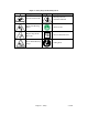
Figure 1: Safety Tags and Warning Labels Tag Description Tag Description Pinch Point Slide Gate Read Operation & Installation Manual Shear Point Rotating Mixer Earth Ground High Voltage Inside Enclosure PE Shear Hazard Rotating Auger Chapter 1: Safety Protected Earth Ground Lifting Point 8 of 60
1-2 Warnings and Precautions Our equipment is designed to provide safe and reliable operation when installed and operated within design specifications, following national and local safety codes. This may include, but is not limited to OSHA, NEC, CSA, SPI, and any other local, national and international regulations.
1-3 Responsibility These machines are constructed for maximum operator safety when used under standard operating conditions and when recommended instructions are followed in the maintenance and operation of the machine. All personnel engaged in the use of the machine should become familiar with its operation as described in this manual. Proper operation of the machine promotes safety for the operator and all workers in its vicinity.
Learn and always use safe operation. Cooperate with co-workers to promote safe practices. Immediately report any potentially dangerous situation to your supervisor or appropriate person. REMEMBER: • NEVER place your hands or any part of your body in any dangerous location. • NEVER operate, service, or adjust the rate monitor without appropriate training and first reading and understanding this manual.
Maintenance Responsibility Proper maintenance is essential to safety. If you are a maintenance worker, you must make safety a priority to effectively repair and maintain equipment. Before removing, adjusting, or replacing parts on a machine, remember to turn off all electric supplies and all accessory equipment at the machine, and disconnect and lockout electrical power. Attach warning tags to the disconnect switch.
Chapter 2: Functional Description 2-1 Models Covered in This Manual This manual provides operation, installation, and maintenance instructions for rate monitors of various extrusion rates and specifications. See below for a list of available models. • GH-M Rate Monitor Units • GH Full Control Units with or without Line Speed Control • GH-F Gravimetric Feeder Units Model numbers are listed on the serial tag.
Customer Service The intent of this manual is to familiarize the operator and maintenance personnel with these rate monitors and help your organization get the maximum service from your equipment. If you have any questions regarding installation, service, repair, custom equipment, or applications, please do not hesitate to contact us for the information required. Prices for additional equipment, accessories, or repair parts will be furnished promptly upon request.
Figure 2: Equipment Specifications Model Maximum Extrusion Rate, lbs/hr (kg/hr) 10 20 40 600 (272) 1200 (680) 2500 (1134) Weigh Hopper Capacity, cu.ft. (Liters) 0.35 (10) 0.7 (20) 1.41 (40) 10 20 40 Load Cell Capacity, kgs Approximate Dimensions, in. (mm) Height (5) 1 @ 10 kg 1 @ 20 kg 1 @ 30 kg 34.5 (875) 51.5 (1308) 56.5 (1435) Width (5) 26.0 (650) 37.5 (952) 37.0 (940) Depth (5) 22.0 (560) 37.0 (940) 40.0 (1016) Typical Weigh Hopper Size, lbs.
• Optional Ethernet communications System Component Description This section describes the various components of the rate monitor system. Extruder Inductive Proximity Switch The extruders RPM must be reported to all GH, GH-M, and GH-F Systems for them to function. To accomplish this, an inductive proximity switch is provided to let the controller know the RPM of the extruder. This switch should be field mounted in an appropriate way to read the extruder’s true RPM.
OPEN Dump cone gate open all the time CLOSE Dump cone closed all the time Each surge hopper is supplied with a lid. Standard lids contain a cutout to accept a vacuum receiver. A blank lid may also be provided if specified. If the rate monitor is being refilled from a mezzanine-mounted GH Hopper, the surge hopper lid will have a tube stub on it. The surge hopper will be mounted on the frame at the factory. The 24V dc solenoid will also be factory wired.
After installation and setup, the GH-M will begin monitoring the system process once the rate monitor detects an extruder speed. The following figures show some typical screens of the GH-M rate monitor. Figure 8: Typical GH Series Controller Touch Screen Display Figure 9: Controller Pushbuttons & Touchscreen Tags Button Function (Power On) (Power Off) Turns power on to the GH Hopper controller. (Found on the back of the controller.) Turns power off to the GH Hopper controller.
Figure 10a: Typical GH-M Operator Screen Figure 10b: Typical GH Full Control Operator Screen Figure 10c: Typical GH-F Gravimetric Feeder Operator Screen Chapter 2: Functional Description 19 of 60
Figure 10d: Operator Screens Common to all GH Systems Chapter 2: Functional Description 20 of 60
Figure 11: Typical Setup Screens Chapter 2: Functional Description 21 of 60
2-4 Optional Components The following is a list of options, which your rate monitor may have been equipped with: Ethernet Module In lieu of an inductive proximity switch, the extruder’s RPM may be written through communications. To accomplish this, an Ethernet module and connecting cable (to PLC) is offered as an option.
Pneumatic Slide Gate below surge hopper The surge hopper can be equipped with a pneumatic slide gate in lieu of the air cylinder and urethane dump cone. The knife gate is opened and closed by the PLC. A 24 VDC solenoid is used to open and close the knife gate. WARNING! Slide gates create a pinch-point hazard Low Level Proximity Sensors Detects material supply problems before rate monitor hoppers are empty. A 24VDC capacitive proximity switch is utilized for this option.
Chapter 3: Installation 3-1 Uncrating the Equipment Rate monitors are shipped mounted on a skid, enclosed in a plastic wrapper, and contained in a crate. 1. Remove crate from around the rate monitor. 2. Secure strap of proper lifting capacity. Caution! Use approved safety straps or chains to lift the rate monitor. 3. Lift the rate monitor until strap is taut. 4. Remove bolts attaching bottom of the rate monitor to shipping skid.
Machine Mount The GH Hopper must be machine mounted. There are a few items to review before placement and mounting of the rate monitor system begins. First, verify the machine flange dimensions match the cast spool-mounting flange. Verify that the machine throat is physically capable of supporting the rate monitoring system with a full load of material and vacuum loading equipment installed. Note: While in operation, the GH system applies horizontal and vertical pressures to the mounting flange.
supply wiring to the control panel. Care must be taken to ensure that the supply wiring does not interfere with the low voltage DC wiring. The GH is supplied with a plug that functions as the disconnect device. The mating receptacle must be installed no higher than 5’ feet (1.6 m) above the floor. Make sure your installation conforms to your regional electrical standards. Please refer to the supplied electrical schematics for detailed connection points for the supply power.
3-5 Initial Set-up This section will discuss the mechanical setup and control system setup of the rate monitor system. After reading this section, you should be familiar with the mechanical setup and the electronic control setup of the rate monitor. Mechanical Set-up Weigh Hopper Installation It is necessary to install the weigh hopper. Remove the weigh hopper from the shipping box and install it onto the load cell bracket.
If an Ethernet module was purchased with the system, the proper setting has to be changed to measure the extruder’s RPM with communications. For details on changing the settings for measuring the extruder’s RPM, please refer to the Addendum 7-4. The controller will be factory set to use the Ethernet module if it has been supplied. Final Connections Connect the rate monitor to the appropriate power source.
Controller Set-up This section describes the proper setup of the GH system control parameters. These parameters are operator changeable; however, these items should only require setup during the initial installation. Only authorized personnel should change them. For security reasons, the menu that is used to access these parameters is password protected. Many of the variables and setup parameters have been preset at the factory and do not need to be changed.
GH Controller Menu Structure “Recipe” Page (Start) ¾ ¾ ¾ ¾ ¾ ¾ ¾ ¾ Extruder RPM is displayed Extruder throughput is displayed Line Speed is displayed (GH Full Control with Line speed option Only) Weight Per Length, Weight Per Area, or simple throughput is displayed on GH Full Control versions depending on setup parameters GH-F Target throughput and percent is displayed (GH-F Only) Access “Inventory” Page Access “Setup” Page “Next” to access “Inventory” page.
GH Calibration The load cell on a GH Hopper is FACTORY CALIBRATED. Since the load cell can be subject to shock loading during shipping, moving, etc., we recommend that they be recalibrated. The heart of the rate monitor system is the load cell and the supplied calibration weight. Since the load cell is weighing the amount of material entering the process, proper calibration of the load cell is essential for the correct and accurate operation of the rate monitor.
Figure 15: Display Calibration Menu Screen Go back to the Setup Directory 3. Once in “Scale Calibration”, enter in the scale calibration weight value stamped on the side of the weight. 4. The controller will prompt you to empty the weigh hopper and press “OK”. 5. After touching OK, the controller will display “PLEASE WAIT...” 6. Next, the controller will ask you to hang the calibration weight on the weight hopper and press OK. 7.
5. Add the calibration weight to the weigh hopper and write down the value displayed in “weight”, as in step 4. 6. Subtract the values recorded in step 4 from step 5. This is the measured weight. If the measured weight is within a 0.003 pounds of the weight stamped on the calibration weight, then you are within spec. If not, follow the steps above to calibrate the rate monitor. (If your rate monitor is frequently out of calibration, verify the operator is being cautious removing the weigh hopper.) 7.
Extruder Setup Use this page to setup the Maximum Extruder RPM. This is critical for GH Monitor units and GHF feeder units. This value is automatically calculated with GH Full Control units. Also for GHF Feeder units you will need to program in the maximum LBS/HR of the extruder for the feeder’s target LBS/HR calculation. Figure 17: Extruder RPM Setup Hauloff Setup and Encoder Calibration Page (GH Full Control ONLY) Use this page to enable the hauloff option of the GH Full Control Unit.
Alarm Setup This screen allows the operator to configure the alarm settings for the rate monitor. To configure the alarms do the following: 6. Enter the Setup Menu. 7. Once in the Setup menu, press “Alarm Setup.” This will take you to the “Alarm Setup” screen. Figure 18: Alarm Setup Screen Changes weigh hopper weight for no material alarm. Change the Alarm Silence Display 8. Press the “Done” key at the bottom to exit this screen.
Setting Date and Time The Set Date & Time feature is located in the “Panel View Config” menu of the Setup Screen. This feature allows the operator to set the rate monitor’s internal time clock and date. The clock data must be entered in the traditional Hours, Minutes, and seconds. The date must be entered in Years, Months, and Days. All values in this screen can be entered by pressing on the related button and choosing the correct number.
Chapter 4: Operation 4-1 GH-M Operation Procedures The system will begin monitoring the process rate once an RPM reading from the Extruder is detected. Again, this RPM must be communicated to the PLC through the supplied inductive proximity switch, or through the optional Ethernet module. The extruder icon on the recipe page will become animated, indicating the extruder is running and the measured Extruder RPM will be displayed.
4-2 GH Full Control Operation Procedures The system will begin monitoring the process rate once the GH System is placed into “RPM Mode” and a target RPM is entered into the controller. If started in “RPM Mode” then the GH should automatically load the hopper when necessary. The system can also be started in “Monitor Mode” by placing the GH into “Monitor Mode” and then running your extruder using the existing control equipment such as the original speed pot.
is that the extruder speed will be slowly adjusted as the output of the extruder drops over time due to the screen pack becoming clogged. NOTE: The GH System can be started using your older speed pots by first placing the system into “Monitor Mode”. After you receive a “Steady Process” in “Monitor Mode” you can then transfer to “Step 1” mentioned above. Starting the system in “Monitor Mode” takes longer and requires a double stabilization step.
4-4 Common Screens Figure 34: Typical Manual Control Operator Screen While the rate monitor system is in operation, there are a couple of displays available to the operator. These displays are selected simply by pressing the “NEXT” key when the unit is running. The default display shown when the rate monitor is in run mode is the Recipe Screen. .
Alarm Flags An alarm message will be shown if any alarm condition occurs. A message will pop up on the screen until the alarm condition is resolved. The operator can press “OK” on this pop-up to hide the screen temporarily, but if the alarm condition is still unresolved, then the message will reappear after a short delay. During an alarm condition, a visual alarm will be activated.
Chapter 5: Maintenance 5-1 Preventative Maintenance Schedule The mechanical design of the GH Hopper is very simple and very little maintenance is required. The only moving parts are the metering gates, weigh hopper dump valve, and mixer agitator. The checklist below contains a list of items which should be inspected and/or replaced to keep your GH Hopper operating at peak efficiency. Perform each inspection at the regular intervals listed below.
5-2 Preventative Maintenance Our GH Hoppers need periodic maintenance to provide long dependable service. Check these elements regularly: • Check functionality of safety circuit daily. • Maintain proper air pressure and drain water from trap assembly on regulator – as required. WARNING! Always remove plug and disconnect power before servicing hopper. WARNING! Always read operating manual before operating or servicing hopper.
Input Signals to Programmable Controller The rate monitor system has two main input signals that it uses from the extrusion process: the weigh hopper load cell, and the extruder speed reference. This, of course, does not include the operator touch-screen input. The extruder speed reference is generated from the supplied inductive proximity switch, or is wrote to the PLC through the optional Ethernet module. Load cells require +12 volts DC to operate. This is known as the load cell’s excitation voltage.
Chapter 6: Troubleshooting 6-1 Introduction The utmost in safety precautions should be observed at all times when working on or around the machine and the electrical components. All normal trouble-shooting must be accomplished with the power off, line fuses removed, and with the machine tagged as out of service. The use of good quality test equipment cannot be over-emphasized when troubleshooting is indicated.
Problem PLC Module Loaded Corrective action Normal after a software upgrade. Follow on-screen instructions. Weigh hopper occasionally overfills. Lower the hopper size under “Hopper Setup” Problem Corrective action Recorded Inventory Totals don’t match what I’ve actually used Check the hopper’s scale calibration and verify that the hopper is not overfilling. If the hopper is overfilling, adjust your hopper size.
Chapter 7: Appendix 7-1 Warranty and Spare Parts Unless otherwise specified, this product includes a Standard ONE YEAR PARTS WARRANTY. Warranty Specifications The manufacturer hereby expressly warrants all equipment manufactured by it to be free from defects in workmanship and material when used under recommended conditions, as set forth in the operating manuals for such equipment.
Customer Responsibilities Any sales, use, or other tax incident to the replacement of parts under this warranty is the responsibility of the purchaser. Annex B Information The following design information is provided for your reference: 1. No modifications are allowed to this equipment that could alter the CE compliance 2. Ambient temperature: 40 degrees Celsius – Maximum (104 degrees Fahrenheit) 3. Humidity range: 50% relative humidity 4. Altitude: Sea level 5.
Figure 57: Typical Surge Hopper Assembly Parts List # 2 3 4 5 DESCRIPTION Lid (Smaller vacuum receivers) Lid (Larger vacuum receivers) Lid (Tube Stub for Mezz. Mounted GH Hopper) 1/8” NPT fitting 1/4” NPT fitting Bulkhead Brass elbow 6 24V DC Solenoid 7 8 Dump cone Air cylinder 1 010 08223-1 NA 08223-2 020 872.00769.00 872.00783.00 35085K, 35086K 35154, 35155 35146 35118 040 872.00830.
7-2 Addendum (Service Supervisor Information) Note: Untrained personnel of the rate monitor controller, should not use this section of the manual and/or program can be compromised! Note: Hidden, programmable features and hidden menu pages should not be made available to floor operators. These pages include the Service Supervisor Information addendum located in this section.
Enter the long password “3145348” and press “Enter”. The factory setup section displays the “Engineering Only” screen. The screen similar to that shown below should be displayed and use the keystrokes described herein to change or toggle the parameters. Figure 68: Typical Engineering Only Setup Screen Go back to Setup Directory Select the desired menu to advance to the screens listed below.
Extruder Pulse Count Method This method updates the weight every “Number of Pulses for Calculation” detected by the extruder proximity switch. This is not the most automated method of the 3 choices, but has it’s advantages. If you are using an unusually large extruder and running it in production at a very low speed then this method works best because the snapshot is taken at the same rotational position of the extruder and eliminates errors in measurement that are caused by the pulsing of the feed throat.
recommended) and it will not cause any error in the displayed measurement. Another more common procedure would be if an operator intermittently adds a processing agent to the extruder by dumping it directly into the weigh hopper. This will not cause any error due to the measurement algorithm that was previously mentioned. Max Allowed WTP/RPM If a lbs/hr per RPM value is every calculated above this setting then the GH will ignore the sample.
Figure 72: Typical Analog Options Analog options screen This screen is not used with the GH-M Rate Monitor. Adjust appropriately for GH Full Control units and GH-F units. Figure 73: Typical Diagnostics Screen Go back to Engineering Only Directory Diagnostics Screen Use this screen for trouble shooting and making tuning adjustments. Typically make an adjustment, reset high/lows, and then weight for some time to observe this page.
Customer Setup Menu Password Protection The Setup screen allows you to change the default User Password that the GH Hopper uses to lock out certain screens. The password by default is “5413”. To change the password, follow the steps listed below: 1. Set the Selected Operator to “USER” by touching the box located next to “Select Operator”. 2. Touch “New Password” and enter in a new password. 3. Touch “Verify Password” and enter in the same password. 4.
7-3 Allen-Bradley Communications Manual The AB rate monitor uses a Micrologix 1500 LRP processor that communicates with the outside world using DF1 protocol with Ethernet hardware. Its Ethernet speed is 10/100 Mbits/second. The rate monitor must be purchased from ACS with the Ethernet option. If this was not done at the time of purchase it can be added afterwards by consulting the factory.
6. 7. 8. 9. 10. 11. 12. 13.
INVENTORY INFO 1. clear_inventory,b3:0/3 (toggle this to clear all inventory, you must also reset this bit after completion) 2. hopper_inventory,f25:0 3. hauloff_accumalated_length,f31:4 EXTRUDER SETPOINT INFO 1. entered_extruder_rpm_target,f13:12 (write desired rpm here) 2. extruder_rpm_target,f13:4 3. extruder_rpm_instant,f13:1 (write rpm value here if you are not using the extruder prox signal for the calculation, NOT FOR GH-F GRAVIMETRIC FEEDER UNITS) HAULOFF SETPOINT INFO 1.
WRITING SETPOINTS EXPLANATION Extruder RPM set points, recipe set points, and haul-off set points can be wrote to while the unit is in stop mode. After engaging either RPM mode or Weight mode then the appropriate values will be applied. While in RPM mode the target recipe value will be overwrote by what the current actual running value is. This ensures that when you transfer to “Weight Mode” that the line set points do not change. This acts as a virtual cruise control for your line.
Technical Assistance Parts Department Call Spare Parts Express toll-free 8am-8pm EST (800) 423-3183 or Phone: (810) 720-7300; Fax: (810) 720-2598. OEM quality replacement and spare parts ensure operation at design specifications. Please have the model and serial number of your equipment when you call. Consult the Customer Parts List included in your information packet for replacement part numbers. Service Department Call toll free (800) 423-3183 8am-8pm EST – Emergency service available 24 hours a day.