SDD Series Digital Dosing Additive Feeders Part Number: 882.00276.00 Bulletin Number: BF3-600.2 Effective: 11/01/06 Write Down Your Serial Numbers Here For Future Reference: _________________________ _________________________ _________________________ _________________________ _________________________ _________________________ We are committed to a continuing program of product improvement. Specifications, appearance, and dimensions described in this manual are subject to change without notice.
Table of Contents SECTION 1: INTRODUCTION …………….……………………….……….........................3 1.1 C150 Controller... .................................................................................... .5 1.2 Keys and Symbols ................................................................................... 6 SECTION 2: QUICK START-UP……………………………………...…….........................8 BASIC INPUT PARAMETERS – INJECTION MOLDING...……...……...12 BASIC INPUT PARAMETERS – EXTRUSION...................……...……...
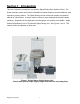
Section 1: Introduction This User’s Manual is intended for use with the Digital Dosing Disc Additive Feeder. The feeder precisely meters and controls the addition of master batches, chemical additives, and regrinds to primary plastics. The Digital Dosing unit can meter both powder and granular material of various sizes. It can be used on extrusion, blow molding and injection molding machines.
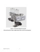
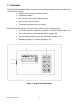
Figure 2.
1.1 Controller The Digital Dosing additive feeder consists of a controller(s), dosing motor(s), and feeder(s). The controller is used to: • Configure the unit to the desired process. • Calibrate the feeder • Run, monitor, and stop the dosing process • Enter, recall, and run recipes • Troubleshoot problems via error codes A keypad and LED display (see Figure 3) are used to enter, or change, data. • The control system is switched on (position “1") with the On/Off switch.
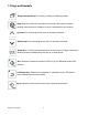
1.2 Keys and Symbols Recipe Storage/Recall: For saving, recalling or modifying recipes. Stop: Stops the continuous operation of the feeder. Will reset the totalizer showing metered amount of additive to zero if depressed for two seconds. Up-arrow: For increasing the set value in decimal increments. Down-arrow: For decreasing the set value in decimal increments. Arrow Key: For fast increasing/decreasing of the set value in larger increments. Must be pressed simultaneously with the up- or down-arrow.
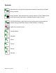
Symbols Lights when the run signal from the process machine is received by the Digital Dosing controller. During operation, lights when the disc is dosing material. During calibration and recipe input/viewing, lights when a calibration weight is input or viewed. (EXTRUSION ONLY) Lights when a screw speed signal is received from the extruder during proportional extrusion control (tracking, or following) Lights when an alarm occurs.
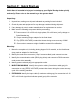
Section 2: Quick Start-up Quick Start is intended to help you in starting up your Digital Dosing feeder quickly and easily. Please refer to the manual to go into greater detail. Unpacking: 1. Unpack box, making sure all parts indicated on packing list are included. 2. Check all parts and equipment for any damage sustained during shipment. 3. If any damage is noted, contact manufacturer for replacement or service. 4.
Recipe Setup for Injection Molding: 1. Turn power switch to ON position. 2. Press Input to display # 1, “Additive %”. Using arrow keys, set additive ratio. 3. Press Input to display #2, “Shot size of current mold”. Using arrow keys, set the total shot size (parts and runners) of the current mold capacity in grams/pounds. 4. Press Input to display # 3, “Screw recovery time”. Using arrow keys, set the screw recovery time (in seconds). 5. Press Input to display # 4, “Calibration weight for additive”.
Recipe Setup for Extrusion: 1. Turn power switch to ON position. 2. Press Input to display # 1, “Additive %”. Using arrow keys, set additive ratio. 3. Press Input to display # 2, “Throughput of extruder”. Using arrow keys, set the total extruder throughput in g/min or lb/min. 4. Press Input to display # 3, “Extruder screw speed”. Using arrow keys, set the extruder screw speed RPM expected during production. NOTE: For Extrusion - Constant operation, the above step will be skipped. 5.
7. After all five samples have been completed; press “run” once more and this will save the calibration weight of the material to the recipe. The calibration light will go out and the screen will now show the total amount of additive dosed. The Digital Dosing feeder is now ready to begin operation. 8. Please refer to “Operation Manual” for all supplementary information regarding general operation, cleaning/maintenance, and troubleshooting. 9.
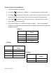
Basic Input Parameters for Digital Dosing Feeder with Injection Software (P1._ _ - Older units) or (P2._ _ - newer units) Hold Stop and Input buttons until “7” flashes - Enter the input number for the specific motor from the table below. - This value sets the impulses of the encoder. Manufacturer Bauer Bauer Bauer Bison Bison Bison Bison Motor Color Blue Blue Blue Black Black Black Black RPM 6.4 11.5 35.
Press Input button -When “9” flashes, enter the configuration value. - Please see the list: “Determining Configuration Value” for more information. Press Input button - When “10” flashes, enter 1 if a blue Bauer motor is intended for use. - If any another motor is intended for use, enter 0.
Press Input button - When “11” flashes, enter 50 - This value is the minimum input frequency. Press Input button − When “12” flashes, enter 5.56 − This value is the span factor. Press Input button − When “13” flashes, enter the communication address. − If Euromap17 is not intended to for use, enter 0. − This value is the communication address. Only enter a value here if Euromap17 report is in use.
Press Input button − When “14” flashes, enter 220 − This value is for the material contents of the mixing hopper. − Only in case of mounting on a micro mixing-hopper.
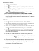
Basic Input Parameters for Colorblend C-150 with Extrusion Software (E1._ _ - Older units) or (E2._ _ - newer units) Hold Stop and Input buttons until “7” flashes - Enter the input number for the specific motor from the table below. - This value sets the impulses of the encoder. Manufacturer Bauer Bauer Bauer Motor Color Blue Blue Blue RPM 6.4 11.5 35.
Press Input button - When “9” flashes, enter the configuration value. - Please see the list: “Determining Configuration Value” for more information. Press Input button - When “10” flashes, enter 1 if a blue Bauer motor is intended for use. - If any another motor is intended for use, enter 0.
Press Input button - When “11” flashes, enter 50 - This value is the minimum input frequency. Press Input button − When “12” flashes, enter 10 − This value is the span factor. Press Input button − When “13” flashes, enter the communication address. − If Euromap17 is not intended to for use, enter 0. − This value is the communication address. Only enter a value here if Euromap17 report is in use.
Press Input button - When “14” flashes, enter 220 - This value is for the material content of the mixing hopper. - Only in case of mounting on a micro mixing-hopper. Press Stop to exit parameters, “18” will flash, then it automatically returns to the totalizer screen.
Section 3: Initial Installation and Operation 3.1 Initial Installation Hopper Piece Processing Machine Direction of Material Flow Figure 4. Digital Dosing Unit Assembly 1. The Digital Dosing additive feeder is not affected by machine vibration, therefore best performance is achieved by mounting the unit directly to the feed throat of the molding machine or extruder (see Figure 4). The inlet into the process machine must be greater than 2” diameter; otherwise, an adapter might be necessary.
4. Electrical connection to process machine: • Injection Molding: Connect the cycle/run slave cable (thin two-conductor cable) to a set of DRY (NO VOLTAGE) contacts that CLOSE for the duration of screw recovery. See Figure 5, electrical diagram. J12-3 J12-2 Relay contact Injection molding Machine Digital Dosing controller (Electrical diagram of connections) Figure 5.
J12-4 _ J12-3 + 0-10 VDC or 0-20 mA Extruder output Digital Dosing controller (diagram of analog inputs) Figure 6. Analog Inputs 5. Make sure the unit is turned OFF before plugging it in. The switch toward the rear of the controller unit should be in the OFF, or “O” position. Standard operation voltage is 110 or 220 VAC, 50/60 Hz, single-phase power. Special voltages are available, refer to voltage label on the feeder to determine the correct operating voltage.
Signal Converter with DC Power Supply This module requires a separate 24 VDC power supply. Vendor: Phoenix Contact Order Designation: MCR-FL-C-UI-2UI-DCI-NC Supply Voltage: 20 to 30V DC Input 4-20 mA, 0-10V (Quantity: 1) Output 0-20 mA, 0-10V (Quantity: 2) 24 VDC Mini Power Supply A Phoenix Contact power supply for the Phoenix Contact signal conditioner listed above.
• This section will show how to calibrate the unit, bring the unit on line, enter a recipe, and store and recall recipes. 3.3 Injection Molding During each molding cycle the Digital Dosing unit doses the correct amount of additive evenly throughout the screw recovery cycle. The Digital Dosing unit determines the correct amount of additive from the recipe and automatically adjusts the duration and speed of dosing by measuring the molding machine screw recovery time each cycle.
Step 2: • Press Input • The symbols “g,” or “lb”, “min” and the screw symbol flash. • After the “2”quickly flashes on the display, a number in the format xx.xxx will again. come up on the display. • Enter the shot weight using the arrow keys. The range of values that can be entered is 001.0 to 6500 grams (0.01 to 14.30 pounds). Step 3: “3” = screw recovery time in seconds • Press Input • The screw and “s” symbols flash. • After “3” flashes quickly on the display, a number in the format xxx.
Step 4: “ 4 “ = calibration weight in grams or pounds • • Press Input a fourth time. The symbols “g” or “lb”and flash. • After “4” quickly flashes on the screen, a number in the format xxxx.x will come up on the display. • Enter the calibration weight in grams. If the calibration weight is unknown, enter “valve” from (section 5.7 knowing you Disc size) to obtain a starting weight. • The range of values that can be entered in this field is 00.0 to 400.0.
Step 6: • Pressing • After the “6” flashes on the screen, a number in the format xxx.xx will come up again, will activate the printing option if it is available. on the display. • By using the arrow keys, you can choose your printer parameters. Step 7: 1. Pressing again will first display the number “18” and then will display the total throughput in kilograms (totalizer).
Operation - Injection Molding 1. Ensure that the unit is properly installed (Section 3.1), a recipe is entered (section 3.3.1), and the feeder is calibrated (Section 3.6), before attempting to begin operation. 2. If desired, clear the totalizer by holding the Stop key ( ) continuously for five seconds until the display is reset to “00.00.” 3. Place the Digital Dosing feeder into operation by pressing the Run key ( ). The green LED will light when the unit is ready to dose.
• To stop the dosing process, press • While the unit is dosing, the current recipe can be viewed, but not modified by pressing . . The recovery time displayed in the current recipe is the average of the last five shots measured from the molding machine. To change the recipe, the unit must be taken off line by pressing the stop key. The run LED will then go out. NOTE: See Appendix A, Troubleshooting, for information on problems or errors encountered and their resolution. 3.
• Enter the additive percentage by using the Arrow Keys . The range of values that can be entered is 0.01 to 50.00%. The arrow keys are used to change all process variables. The double arrow key allows the user to ramp up or down at a faster rate. Step 2: or • • Press again. The symbols “g,” or “lb”, “min”, and • After “2” flashes quickly on the display, a number in the format xxx.xx will come up on flash. the display. • Enter the total extruder throughput in grams per minute or pounds per minute.
Step 4: • Press again and the symbol “s” will light up and the number “5” will be displayed if you have a blending unit and have invoked this option. • After “5” flashes on the display, a number in the format xxx.xx will come up on the display. • Enter the maintained running time of the blending unit in seconds using the arrow keys. This is how long the blender will run after each dosing cycle and should be adjusted for the best possible blend.
Step 6: 6. Press again. 7. The number “18” will be displayed before the total throughput in kg is displayed.
Operation – Extrusion - Constant 1. Ensure that the unit is properly installed (Section 3.1), a recipe is entered (Section 3.4.1), and the feeder is calibrated (Section 3.6), before attempting to begin operation. 2. If desired, clear the totalizer by pressing continuously for 5 seconds until the display is reset to “00.00.” 3. Place the Digital Dosing unit into operation by pressing .
3.5 Extrusion – Proportional (Extruder Follower Option) Recipe Input – Extrusion Proportional To enter a recipe for Extrusion Proportional, the following process data is required: • Percentage of additive • Expected throughput of the extruder during production • Extruder screw speed during production • Calibration weight in grams Step 1: • Press the Input key, • The • After “1” flashes quickly on the display, a number in the format xxx.xx will come , once. symbol flashes. up on the display.
• After “2” flashes quickly on the display, a number in the format xxx.xx will come up on the display. • Enter the expected extruder throughput during production in grams per minute or pounds per minute. The range of values that can be entered is 001.0 to 6500 grams per minute (00.01 to 14.30 lb/m). Step 3: • Press • The machine displays a flashing screw • After “3” flashes quickly on the display, a number in the format xxx.xx will come a third time. . up on the display.
Please note: Parameters 5 and 6 will only be displayed when a mixer and or a printer is configured. Step 5: • Press again and the symbol “s” will light up and the number “5” will be displayed if you have a blending unit and have invoked this option. • After “5” flashes on the display, a number in the format xxx.xx will come up on the display. • Enter the maintained running time of the blending unit in seconds using the arrow keys.
Step 7: • Press a fifth time to return to the totalizer. Operation – Extrusion – Proportional (Extruder Follower Option) ; Ensure that the unit is properly installed (Section 3.1) ; A recipe is entered (“Recipe Input-Extrusion Proportional” Section ) ; The feeder is calibrated (Section 3.6), before attempting to begin operations. 1. If desired, clear the totalizer by pressing continuously for 5 seconds until the display is reset to “00.00.” 2.
3.6 Calibration All feeders must be calibrated before any blending recipes can run using the Digital Dosing additive feeder. NOTE: The calibration weight (metered material weight for one revolution of the dosing disc) must be determined separately for each material to be dosed since calibration weight differs from material to material. The following equipment is needed for calculating the calibration weight: • Scale with a minimum accuracy of 0.
• This sample should be returned to the material hopper without weighing. This sample is used only to ensure that all disc pockets are completely filled. • Replace container in calibration box (or under material outlet tube) • Press • The disc will rotate one full revolution. After the disc has stopped rotating, a Step 3: to take a sample for weighing. number in the format “xx.xx” will appear on the screen along with a flashing and “g.
Step 6: After the fifth calibration sample press “ RUN “ the controller will automatically finish the calibration cycle and be ready to run. The following are methods used to interrupt the calibration cycle. • Pressing the stop button will stop proportioning and not accept the calibration weight. • Pressing the calibration button will stop proportioning and accept the calibration weight. NOTE: It is normal for calibration weights to vary slightly from sample to sample.
Section 4: Advanced Operations/ Control Functions 4.1 Recipe Storage and Recall A maximum of ten (10) recipes can be stored and retrieved with the Digital Dosing controller in the Recipe Storage/Recall mode. Recipes are stored using a two-digit identification number. Pressing at any time will exit the Recipe Storage/Recall mode. Recipe Storage To store the current recipe: Step 1: • ). A two-digit number (01 through 10) will Press the Recipe Storage/Recall key ( appear on the screen.
Step 3: or • Press and hold the button • The recipe is now stored under the selected ID number. until the totalizer display returns to the screen. Recipe Recall Step 1: or • Press the stop button to stop any current applications. • Press the Storage/Recall key ( • A two-digit recipe ID number will appear on screen. • Use the Arrow Keys Step 2: ) once. Step 3: Digital Dosing Units to select the desired recipe number.
Step 4: • Press and hold • The recipe is now active and can be run or edited. until the totalizer appears on the screen. NOTE: The recalled recipe now becomes the active recipe. 4.2 Clearing the Totalizer • The totalizer displays the total amount of additive dosed since the last time the totalizer was cleared. • The totalizer can be cleared by pressing Stop continuously for 5 seconds until the display is reset to “00.00.” The totalizer can be configured to read throughput in grams or pounds.
4.4 Optional Equipment, Level Switches and Communications Options Optional equipment for the Digital Dosing Additive Feeder includes: Alarms Several alarm options are available for the Digital Dosing feeder. The standard unit comes with a flashing alarm symbol on the faceplate. Options include both audible horns and flashing lights. An optional no voltage alarm relay can be connected to the user’s central alarm system. Level switches (probes) To adjust the level switches: 1. Turn the controller ON. 2.
NOTE: Turning the trim-pot to the left decreases the switching sensitivity; turning it to the right increases the switching sensitivity. 5. Fill the dosing station until the level probe is two-thirds covered. The yellow control lamp should now switch on again. If not, repeat Step 4. 6. Reinstall the plastic screw (M3). NOTE: The sliding switch under the cover must be set on “0”.
Section 5: Maintenance 5.1 Maintenance Intervals Check warning signs on equipment for good legibility Daily: and completeness. Weekly: Check function of the “On/Off” Switch. Check shear plate in “DD” dosing station, and wiper in Every 3 months: “DT” dosing station. Check that all electrical and mechanical connections Every 6 months: are tight. Annually: Check dosing disc in dosing station DD/DT. Each time after material Is changed: Clean the dosing station.
6. Remove the dosing unit from the dosing motor. 7. Remove the cover from the connecting piece (D). 8. Loosen the two screws (C) on the underside of the dosing unit housing (E). 9. Remove the shear plate (A). Installing the shear plate 1. Place the new shear plate in the dosing unit housing. 2. Ensure that the shear plate is positioned correctly. 3. Screw the shear plate in place by means of 2 hexagon socket screws (M5 x 16). 4. Turn the dosing disc to check for smooth movement. 5.
5. Remove the dosing hopper from the dosing unit. 6. Dismantle the dosing unit and remove the shear plate (D). 7. Loosen the two hexagon socket screws (B, M6 x 30) on the top side of the dosing disc (A). 8. Loosen the center hexagon socket screw (C, M6 x 12) and replace by an M6 x 60 screw. 9. Lift the dosing disc (A) from the dosing unit housing (B) by this screw. 10. Clean the shear plate using a cotton cloth. 11. Clean the dosing hopper and the dosing disc in soapy water. 12.
5.4 Changing the Dosing Disc in the “DT” Digital Dosing Station Removing the Dosing Disc 1. Empty the dosing station. 2. Switch the control unit off by means of the on/off switch. 3. Dismantle the dosing unit and remove the shear plate. 4. Loosen the two hexagon socket screws (M6 x 30) on the top side of the dosing disc. 5. Loosen the center hexagon socket screw (M6 x 12) and replace by a M6 x 60 screw. 6. Lift the dosing disc from the dosing unit housing by this screw. Installing the Dosing Disc 1.
Installing Different Types of Dosing Discs Dosing discs of the same type, and thickness (72 pocket), may be exchanged for each other without any problems. If dosing discs with a different compartment number or thickness are installed, this has to be entered in the control system! DD Discs Disc Calibration Number of Number pockets DD 30-030672 1.75 72 DD 30-051040 5.00 40 DD 30-051725 8.00 25 DD 30-051818 15.00 18 1.
8. Tighten down the 3 plastic screws. Make sure that the wiper is fitted parallel to the dosing plate (Use only plastic screws to avoid damage to the extruder or molding machine screw should the mounting screws ever come loose.) 9. Install the dosing container along with the dosing hopper on the dosing housing (pay attention to the guide pins). 10. Mount the profile clamp. 11. Mount the screw at the profile clamp. 5.6 Cleaning the DT Dosing Station 1. Empty the dosing station. 2.
16. Mount the safety screws. 17. Install the dosing container along with the dosing hopper on the dosing housing (pay attention to the guide pins). 18. Mount the profile clamp. 19. Mount the screw at the profile clamp and tighten. 5.7 Exchangeable Stations Dosing discs of the same type may be exchanged for each other without any problems. If dosing discs with a different compartment number are installed, this has to be entered in the control system. 1.
5.8 Replacing Fuses 1. Stop the continuous operation. 2. Wait until the dosing unit has stopped. 3. Switch off the device with the on/off switch. 4. Cut off the voltage supply. 5. Wait at least one minute before starting to work at the unit or controller. 6. Never try to repair a defective fuse. 7. Open the screws (A) and remove the lid (B). 8. Remove the blind lid (C) and open the screws. 9. Move the lid (D) aside. 10. Remove the defective fuse from the fuse carrier. 11.
Appendix A: Troubleshooting During setup and use of the Digital Dosing Additive Feeder, personnel may experience difficulties. Some of the problems encountered may be resolved using the following techniques. A.1 General Troubleshooting - Unit Will Not Operate • Check all connections and process wiring. Note that the process machine input MUST be wired to a DRY contact for Injection Molding (Section 3.1) and Extruder - Constant Applications (Section 3.1).
ERROR CODES Code A001 A002 A003 Definition Strap “safety switch” is missing. The nominal current of the dosing motor (=100%, see name plate) is being exceeded for more than 2 seconds by 30% or for a maximum of 0.5 seconds by 80%. The nominal current of the dosing motor (=100%, see name plate) is being exceeded for more than one minute. A004 Excess temperature.
A.3 Determining the Software Setup Factor The Digital Dosing control unit is configured via a Software Setup Factor (binary code). To determine the Software Setup Factor answer the following questions: If the answer is “yes” enter the code number in the selection column. If the answer is “no” enter “0” in the selection column. When all the questions have been answered and the selection column is completed, add up the total for the selection column. The total is the Software Setup Factor. A.
Extrusion For extrusion applications compute the dosing disc speed using the following formula. Recipe limitations are listed in the table following the recipe. Disc RPM = ( Additive - %) x (Total Extruder Throughput - lb / hr) 13.22 x (Disc Calibration Weight - g) Recipe Limitations Extrusion Motor Assembly Speed (RPM) 11.5 35.5 Digital Dosing Units 57 Maximum Speed (RPM) 11.5 35.
Appendix B: Basic Parameter Settings Extrusion Mode: You need an extruder signal that is proportional to the extruder speed to operate in the Extrusion - Proportional mode. You can use any of the following: • Frequency signal (must be 12 VDC square wave) • 0 - 10 VDC signal • 0 - 20 mA current signal Determine the frequency output in the lower working area (A) of the extruder. Record the data. Min.
Frequency [Hz] = Input current [mA] x 10000 [Hz] 20 [mA] Note the data: Min. input frequency = __________ Hz Max. input frequency = __________ Hz Calculate the span factor using the formula: Span factor [Hz / rpm] = Frequency [Hz]____________ Rotational speed of the extruder [rpm]x 10 Note the data: Span factor = __________ Determining the Configuration Value Extrusion (Constant or Proportional): Mark the functions required.
• Throughput: 8000 g/min • Totalizer displayed in lbs • Extrusion mode Raw material probe . . . . . . . . . . . . . . . . . . . . . . . . . . . . . . . . . . . . 1 1 Additive probe . . . . . . . . . . . . . . . . . . . . . . . . . . . . . . . . . . . . . . . . 2 2 Blending unit . . . . . . . . . . . . . . . . . . . . . . . . . . . . . . . . . . . . . . . . . 8 __ Totalizer displayed in lb. . . . . . . . . . . . . . . . . . . . . .. . . . . . . . . . . .16 16 Extruder throughput (1 kg-6.
Optional blending (mixing) unit installed . . . . . . . . . . . . . . . . . . . . . .8 ___ Totalizer displayed in lb (kg default) . . . . . . . . . . . . . . . . . . . . . . . . . 16 ___ Shot weight (1 kg-6.5 Kg) ……………. . . . . .(2.2 lbs-14.3 lbs) …….0 ___ Shot weight (10 kg-65 kg)……………………..(22 lbs-143 lbs). . . . . 32 ___ Shot weight (0.1 kg-0.65 Kg) . ……………… .(0.22 lbs-1.43 lbs)….
Additive probe . . . . . . . . . . . . . . . . . . . . . . . . . . . . . . . . . . . . . . . . 2 2 Blending unit . . . . . . . . . . . . . . . . . . . . . . . . . . . . . . . . . . . . . . . . . 8 __ Totalizer displayed in lb. . . . . . . . . . . . . . . . . . . . . .. . . . . . . . . . . .16 16 Shot weight up to 6.5 kg . . . . . . . . . . . . . . . . . . . . . . . . . . . . . . . . 0 or Shot weight 6.5 to 65 kg . . . . . . . . . . . . . . . . . . . . . . . . . . . . . . . .
Appendix C: Dosing factors, equipment drawings and part numbers Disc Dosing Factor Table 1: Disc Guide Disc DD30-030672 Disc Nomenclature Used in the Controller P030672 # of Holes Diameter Disc Thickness 051040 # of Holes Diameter Disc Thickness Default Calibration # 7.3 grams/rev Min. Throughput with 100% Continuous Running (35 lbs./cu. ft.) Max. Throughput with 100% Continuous Running (35 lbs./cu. ft.) Weight Per Disc Revolution (44 lbs./cu. ft.) Min.
DD30 051818 051818 # of Holes Diameter Disc Thickness 13.42 g/Rev. 0.35 lb/hr 11.40 lbs/hr 17.08 g/rev. 0.44 lb/hr 14.5 lbs/hr 0.75 g/Hole 0.16 kg/hr 5.15 kgs/hr 0.95 g/hole 0.20 kg/h 6.56 kgs/h 0.85 lb/hr 19.60 lbs/hr 1.12 lbs/hr 25.63 lbs/hr 0.39 kg/hr 8.89 kgs/hr 0.51 kg/hr 11.62 kgs/hr 1.76 lb/hr 63.00 lbs/hr 2.20 lbs/hr 80.25 lbs/hr 28.00 g/Rev. 0.80 kg/hr 0.75 lb/hr 28.60 kgs/hr 23.70 lbs/hr 35.63 g/rev. 1.00 kgs/hr 1.00 lbs/hr 36.4 kgs/hr 30.1 lbs/hr 1.40 g/Hole 0.
DT30 204010F 204010 # of Holes Diameter Disc Thickness 0.2 Rev./min (6.4 RPM) 151.15 g/Rev. 4.00 lb/hr 128.00 lbs/hr 188.72 g/rev. 5.0 lbs/hr 160 lbs/hr 15.12 g/Hole 1.80 kg/hr 59.00 kgs/hr 18.87 hole 2.25 kg/h 72.5 kgs/h 10.00 lb/hr 227.74 lbs/hr 12.43 lbs/hr 283 lbs/hr 4.53 kg/hr 103.28 kgs/hr 5.64 kgs/hr 129 kgs/hr 20.00 lb/hr 705.00 lbs/hr 25.00 lbs/hr 886 lbs/hr 9.00 kg/hr 320.00kgs/hr 11.30 kgs/hr 402 kgs/hr 15.64 g/Rev. 0.41 lb/hr 13.20 lbs/hr 19.53 g/rev. 0.
Specification Sheet DIGITAL DOSING UNIT TECHNICAL PARAMETERS Disc Dosing Factor Table 2 Maximum Number of Feed Stations One (1) for Granule Processing Maximum Product Temperature 80oC (or 176 oF) Weight (Approximately) 20 kg (44 pounds) Connected Loads 0.
Starter Calibration Parameters DD Discs Disc Calibration Number DD 30-030673 1.75 Parameters Default Units 1 Additive % Percent 2 Shot size of the current mold Grams/pounds 3 Screw recovery time Seconds Calibration weight for additive Totalizer (display only) Grams Grams/pounds 4 18 Description Using the arrow keys, set additive ratio. Using the arrow keys, set the shot size of the current capacity in grams/min or pounds/min.
Digital Dosing unit parameter setup 1-4 for extrusion proportional Default Units Parameters Description 1 Additive % Percent Using the arrow keys, set additive ratio.
10 5.56 10 5.
Station 1 Digital Dosing Unit SIDE VIEW TOP VIEW 71
Station 2 Digital Dosing Unit SIDE VIEW TOP VIEW 72
General Wiring Diagram for Bauer Motor 73
Dosing Unit Electrical Schematic Chart for Bauer (blue) motors only Drawing No.
Appendix D: Spare Parts List Dosing Disc/Shear Order Numbers Dosing disc 72 chambers CT 100562 49 chambers CT 21710 25 chambers CT 21711 18 chambers CT 2057 Dosing disc, wear-resistant 40 chambers CT 28214 25 chambers CT 27141 18 chambers CT 27142 Shear for DD style unit 18, 25, 40 pocket disc CT 21392 72 pocket disc CT 100875 Replacement Motor Order Numbers Bauer Gear Motors 6.4 RPM CT34300 11.5 RPM CT102241 35.
Control System Order Numbers Fuse F1 F2 F3 F4 F5 F7 Size 5X20 1/4X1 5X20 5X20 5X20 5X20 Voltage 250 V 1/4-250 V 250 V 250 V 250 V 250 V 77 Amps 5A 4A 0.5 A 0.5 A 0.5 A 0.
-Notes- 78
Technical Assistance Parts Department Call toll-free 7am–5pm CST: [800] 783-7835 The ACS Customer Service Group will provide your company with genuine OEM quality parts manufactured to engineering design specifications, which will maximize your equipment’s performance and efficiency. To assist in expediting your phone or fax order, please have the model and serial number of your unit when you contact us. A customer replacement parts list is included in this manual for your convenience.