SCW Series Screw Compressor Central Chiller Part Number: A0551795 Bulletin Number: SC3-635.2A Effective: 10/1/07 Write Down Your Serial Numbers Here For Future Reference: _________________________ _________________________ _________________________ _________________________ _________________________ _________________________ We are committed to a continuing program of product improvement. Specifications, appearance, and dimensions described in this manual are subject to change without notice.
Shipping Information Unpacking and Inspection You should inspect your Screw Compressor Central Chiller for possible shipping damage. Thoroughly check the equipment for any damage that might have occurred in transit, such as broken or loose wiring and components, loose hardware and mounting screws, etc. In the Event of Shipping Damage According to the contract terms and conditions of the Carrier, the responsibility of the Shipper ends at the time and place of shipment.
Table of Contents CHAPTER 1: SAFETY ............................................................... VI 1-1 1-2 1-3 How to Use This Manual .............................................................................................vi Safety Symbols Used in this Manual .................................................................... vi Warnings and Precautions ......................................................................................... vii Responsibility ....................................
-3 4-4 4-5 4-6 Identifying Control Panel Indicator Lights and Switches for the Standard and Advanced Controllers .......................................................................................... 34 Controller Operation (Standard Controller) ............................................................... 36 Using the Standard Touchscreen Interface ......................................................... 36 Main Menu Screen ........................................................................
7-7 7-8 Central Chiller Identification (Serial Number) Tag ..................................................... 76 Technical Assistance ................................................................................................ 77 Parts Department ................................................................................................ 77 Service Department............................................................................................. 77 Sales Department..........................
Chapter 1: Safety 1-1 How to Use This Manual Use this manual as a guide and reference for installing, operating, and maintaining your screw compressor central chiller. The purpose is to assist you in applying efficient, proven techniques that enhance equipment productivity. This manual covers only light corrective maintenance. No other maintenance should be undertaken without first contacting a service engineer.
1-2 Warnings and Precautions Our equipment is designed to provide safe and reliable operation when installed and operated within design specifications, following national and local safety codes. This may include, but is not limited to OSHA, NEC, CSA, SPI, and any other local, national and international regulations.
1-3 Responsibility These machines are constructed for maximum operator safety when used under standard operating conditions and when recommended instructions are followed in the maintenance and operation of the machine. All personnel engaged in the use of the machine should become familiar with its operation as described in this manual. Proper operation of the machine promotes safety for the operator and all workers in its vicinity.
Operator Responsibility The operator’s responsibility does not end with efficient production. The operator usually has the most daily contact with the equipment and intimately knows its capabilities and limitations. Plant and personnel safety is sometimes forgotten in the desire to meet incentive rates, or through a casual attitude toward machinery formed over a period of months or years. Your employer probably has established a set of safety rules in your workplace.
• Clean the chiller and surrounding area DAILY, and inspect the machine for loose, missing or broken parts. • Shut off power to the chiller when it is not in use. Turn the switch to the OFF position, or unplug it from the power source. Maintenance Responsibility Proper maintenance is essential to safety. If you are a maintenance worker, you must make safety a priority to effectively repair and maintain equipment.
Chapter 2: Functional Description 2-1 Models Covered in This Manual This manual provides operation, installation, and maintenance instructions for Screw Compressor Central Chillers. Model numbers are listed on the serial tag. Make sure you know the model and serial number of your equipment before contacting the manufacturer for parts or service. Our screw compressor central chillers are designed to generate cooled water at carefully controlled temperatures for use in plastic processing systems.
Electrical Features • Electronic expansion valve • 2 remote single circuit condensers with variable speed lead fans and fan cycling (aircooled models) • NEMA 12 electrical enclosure • Touch-safe branch circuit fusing • Liquid line solenoid and shut-off valves • Chilled water flow switches Controller Features • Allen Bradley Micrologix 1500 PLC control with PanelView 300 Micro monochrome/key pad interface • Digital low temperature freezestat • 3 year warranty on controller Standard Features on Remote Condens
2-4 Options Options marked with “*” indicate options that can be factory installed or retrofitted in the field.
Fail Safe Operation If a safety device or circuit should fail, the design must be such that the failure causes a “Safe” condition. As an example, a safety switch must be a normally open switch. The switch must be held closed with the device it is to protect. If the switch fails, it will go to the open condition, tripping out the safety circuit. At no time should the safety device fail and allow the operation to continue.
Chapter 3: Installation 3-1 Uncrating the Equipment WARNING!Due to the size and weight of the Screw Compressor Chiller, the manufacturer recommends using bonded professional millwrights to unload and move the chiller. 1. Rig the chiller from the frame only, using spreader bars to prevent load transfer to any chiller components. 2. Rig the frame from at least four points and balance the load before lifting to clear the skid. 3. Use a forklift of adequate size when lifting the chiller by the fork pockets.
3-3 Making Electrical Connections Screw Compressor Central Chilling systems are designed for three-phase voltage operation. Refer to the unit nameplate for proper voltage and amperage requirements. Note: Make sure you provide a correctly sized and protected supply of electrical power to the unit. Refer to National Electric Code (NEC) Article 430-24 through 430-26 for proper feeder conductor and supply disconnect sizing. Maintain a safe ground and disconnect the power supply before servicing the unit.
Note: • Never switch contactor leads or motor leads for reversing rotation. • Do not use contactor or motor leads for phase matching. • Compressor damage will occur if the compressor is run in reverse. The compressor motor protector checks for correct phasing and will not allow it to start in reverse. • If you discover that phasing is reversed, correct it by switching any two main power leads into the disconnect switch or distribution block on the unit. Check your work and proceed to the next section.
Making Process Water Connections All Models All central chilling stations have two chilled water connections per unit, and on water-cooled models, one more set of water connections for condenser water: The chilled water manifold allows one-point connections of Chilled Water piping. The Sch. 40 steel piping includes butterfly valves at each evaporator for flow balancing and circuit isolation; optional pressure gauges can be installed.
Making Tank Piping Connections If you have purchased the Screw Compressor central chilling station with the optional integral pump tank, please proceed with this section. Note: Thermo couplings for chillers must be installed on both the hot and cold sides of the tank. Freezestat Control The unit can be equipped with a freezestat control which shuts down the compressor if the chilled water temperature approaches the freezing point. The chilled water pump on the system will continue to run.
Return (From Process) Bring the chilled water returning from the process to the pump tank warm (From Process) side. This line is sized according to the flow rate from the process to the pump tank. See Page 16 for more information on piping considerations. Caution! Do not use the Screw Compressor Central Chiller to support piping. Makeup Connect a city water source to maintain water level in the pump tank. See page 21 for water treatment considerations.
Water Connection Sizing Considerations Note: • Run all external chilled water connections with adequate size to the process. • Provide the largest possible openings and passages for the flow of chilled water through platens, dies, molds, or other pieces of equipment. • Minimum external pressure drop is critical for proper operation. Galvanic Corrosion Considerations Water circuit piping components are primarily ferrous (iron) and react electro-chemically with non-ferrous metallic materials such as copper.
Condenser Water Out The return outlet, located at the chiller side or rear is connected to a cooling tower inlet, a sewer or other approved discharge receiver. • A water regulating valve is an optional feature in the condenser water out line. • Adjust the butterfly valve for the pressure drop that corresponds to the model number of the chiller (Shown in the table below). Pressure drop is equal to supply pressure minus return pressure.
Installing the Remote Air-Cooled Central Chiller Condensers Remote air-cooled condensers use the surrounding air to cool the refrigerant from the compressor and release the process heat absorbed from the chilled water into the atmosphere. All models have variable speed fans and low ambient controls to allow proper operation down to -20°F (-29°C) outdoor air temperature.
System Configuration The system can be configured in any of the arrangements shown on page XX of the Appendix. The configuration and distance between the chiller and the condenser affects pipe size, refrigerant charge, oil return, and oil charge. Therefore, there are limitations that must be adhered to for reliable and optimal operation. • Leaving water temperature affects discharge line size.
Liquid Line Sizing The liquid line should be sized as small as possible while maintaining acceptable pressure drop to minimize the refrigerant charge. Liquid line risers should not exceed 15 feet from the base of the air-cooled condenser. Horizontal runs do not require a pitch. Insulation is recommended to prevent heat losses/gains and condensation due to unusual ambient conditions. Install a liquid line-charging valve to facilitate refrigerant charging. See Figure 3 for liquid line sizing information.
Discharge Line Sizing For horizontal runs, the discharge line should be pitched downward, in the direction of flow at a rate of ¼” for every 10 feet. This will allow oil to flow towards the condenser. Discharge line sizing is based on the velocity required for sufficient oil return back to the compressor. See Figure 4 for horizontal and vertical flow down discharge line sizing and Figure 5 for vertical flow up discharge line or double riser sizing if required.
Refrigerant Charge Determination The approximate amount of refrigerant charge required by the system varies based on the total length of the refrigerant lines and the size of the chiller. Referring to Figure 6, determine the amount of charge based on discharge and liquid line sizes and lengths. Add these four numbers together to find the total operating charge. Figure 6: Refrigerant Charge Determination (per circuit) Air Cooled Condenser Charge Chiller Charge Horsepower Lbs. of R134a Horsepower Lbs.
Checking Motor Direction Compressor Caution! Check Compressor Rotation Before Starting Unit! Connect a phase monitor and phase incoming power ABC. Note: • Unit must be wired in sequence (ABC) and checked before start up. • Never switch contactor leads or motor leads for reversing rotation. • Do not use contactor or motor leads for phase matching. • Compressor damage will occur if the compressor is run in reverse.
Water-Cooled Central Chiller 1. Check the shipping papers against the serial tag to be sure chiller size, type and voltage is correct for the process. 2. Check the transformer primary voltage connections to be sure they are configured for the electrical power you are using. 3. The voltage at the main power connection must be within plus or minus ten percent (±10%) of the voltage listed on the serial tag. 4. Phase imbalance must be less than two percent (<2%). 5. Unit must be wired in sequence (ABC). 6.
19. Close the discharge butterfly valve then crack it open; open all pump suction butterfly valves fully, then start the pump and observe the gauge. 20. Check for proper pump rotation direction. To confirm proper rotation: a. Observe a pump pressure gauge connected to the suction and discharge sides of the pump casing through two ¼” (approx. 6.4 mm) gauge cocks. b. Close the gauge cock leading to the pump suction and open the gauge cock leading to the pump discharge. c.
13. Check condenser fans for pressure switch settings as shown in the table below: Fan number 1 2 3 4 5 psi 140 150 160 170 Set on Set off KPa bars psi kPa not applicable; Fan 1 is a variable-speed fan 1,069 10.7 105 828 1,172 11.7 115 931 1,276 12.8 125 1,035 1,379 13.8 135 1,138 bars 8.3 9.3 10.3 11.4 14. Connect the main power to the unit and bump-start it to check for proper rotation direction. If the fans are operating backwards, reverse any two main power leads at the incoming terminal block. 15.
2. If the gauge indicates 20 psi (137.9 kPa/1.38 bars) or more below the pump curve, the pump is running backwards. Reverse rotation by interchanging any two power mains to the pump motor or starter. 3. Recheck the pressure to be sure it increased. 22. Check the water level in the pump tank to be sure the pump does not run dry while the system piping is being filled. 23. Open the discharge fully when system is filled. 24. Check your work and proceed to the Startup procedure in the following section.
Chapter 4: Operation 4-1 Start-up Water & Remote Air-Cooled Central Chiller Startup 1. Start the chiller by pushing the Start button on the control panel of the unit. 2. The touchscreen will display the Main Menu screen. 3. If your chiller has been setup to control the pump tank, the recirculation pump will turn on first, then after 5 seconds the process pump will turn on. If configured with a standby pump, the lead/lag will control which pump turns on.
4-2 Controller Description Identifying Control Panel Indicator Lights and Switches for the Standard and Advanced Controllers System On The green System On indicator lights when the main power switch is on and the control circuit is energized. Start The Start push-button lets you energize the unit. Stop The Stop push-button lets you de-energize the unit. Touchscreen Interface The touchscreen interface gives you control over the chilling station.
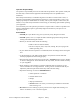
Figure 2: Advanced Touchscreen Controller Screw Compressor Central Chiller Chapter 4: Operation 35
4-3 Controller Operation (Standard Controller) Using the Standard Touchscreen Interface Introduction The Standard touchscreen interface lets you control your Screw Compressor central chilling station. You can do such things as: • Control compressors and optional pumps • View current statuses of operation, such as pressures, temperatures, and capacities • Handle alarm conditions This section lists special instructions for operating the standard touchscreen interface.
Main Menu Screen To start the Standard touchscreen interface: • Push the ON/OFF button on the cabinet. The chillers’ control panel energizes and the System On indicator turns on. The Main Menu screen displays: Main Menu Screen The Main Menu screen lets you gain access to: • “COMPRESSOR STATUS” contains the compressor status display screen • If the chiller was configured to operate the chilled water pump tank, the “PROC PUMP STATUS” is displayed. This screen contains the process pump status.
To view the status of the chiller compressors, start at the Main Menu screen, then: 1. Press the or buttons on the right side of the screen to highlight “COMPRESSOR STATUS” 2. Press ↵ The compressor status screen displays: Compressor Status Screen The Compressor Status screen shows the status for compressors within the system. Only compressors that are included in the system will be shown on this screen. Compressors will display one of the following states: 1.
Process and Recirculation Pump Status Screens Note: If your chiller system was configured to operate the pump(s) of the chilled water pump tank, the user may view the status of the process and recirculation pumps. To view the status of the pumps, start from the Main Menu, then: 1. Press the or buttons to highlight either “PROC PUMP STATUS”or “RECIRC PUMP STATUS”. 2. Press ↵ The Pump Status Screen appears Pump Status Screen Only pumps that are enabled in the system will be shown on this screen.
Active Alarm List and Alarm History Screens These two screens let you view any active alarm conditions as well as the alarm history or the entire history.
Configuration Menu Screen This screen allows the operator to configure the settings for the compressors, pumps, chiller setpoint, and high and low temperature alarm setpoints. Operating the chiller compressors To enable or disable the individual compressors, start at the Main Menu, then: 1. Press the or buttons on the right side of the screen to highlight “CONFIGURATION MENU” 2. Press the ↵ button The configuration menu screen displays: Chiller Configuration Screen 3.
Compressor Enable Screen These screens allow the customer to toggle the compressors between ON-LINE and OFFLINE. As the operator presses the F1 or F2 button, the corresponding compressor state changes between ON-LINE and OFF-LINE. Press F4 to leave this screen. Setting Compressor Rotation Times and Activating Compressor Lead/Lag Operation While in the Configuration Menu, the compressor rotation screen allows the customer to enable or disable the rotation of compressors.
Operating Chiller Pumps To turn on and off the pumps, start from the Main Menu, then: 1. Press the 2. Press or buttons to highlight either “CONFIGURATION MENU”. ↵ 3. Highlight “PUMP ENABLES” 4. Press ↵ 5. Highlight the pump you want to operate. The Pump Enables Screen appears Pump Enables Screen Any pump that is disabled to the OFF-LINE position will not be called to operate. Simply toggle the F1 key on the enable/disable screen to toggle the state of the pump from the ONLINE to OFF-LINE state.
Setting Pump Rotation Times and Activating Pump Rotation Operation While in the Configuration Menu, the pump rotation screen allows the customer to enable or disable the rotation of compressors. While viewing the screen for the applicable rotation, pressing F1 will toggle the rotation function On or Off. Pressing the F2 button will present an entry screen which will allow the entry of a rotation interval. Acceptable range is 50-200 hours.
Viewing and Setting System Temperatures To view the actual process temperature, select the “COMPRESSOR STATUS”, “PROC PUMP STATUS”, or the “RECIRC PUMP STATUS” screens from the main menu. The process temperature is located on the bottom-right of the screen. For example, the compressor status displays: Compressor Status Screen Note: If you have a metric version of the Central Chiller controller, the screens display in converted metric values.
Hourmeters Screen Viewing Compressor Run Times From the Main Menu, use the or buttons to highlight the “HOURMETERS” menu. Scroll to select the compressors. Then press ↵ to display the hourmeter. Note: This is a complete list of all components that may be included in the system. Any component that is not included in the system will not accumulate time. The Compressor Run Time screen displays: Compressor Run Time Display Screen Two hourmeters are kept for each compressor in the system.
Viewing Pump Run Times From the Main Menu, use the or menu. Scroll to select the pump. Then press buttons to highlight the “HOURMETERS” ↵ to display the hourmeter. Note: This is a complete list of all pumps that may be included in the system. Any pump that is not included in the system will not accumulate time. The Pump Run Time screen displays: Compressor Run Time Display Screen Two hourmeters are kept for each compressor in the system. The first is a lifetime meter.
4-4 Controller Operation (Advanced Controller) Using the Advanced Touchscreen Interface Introduction The Advanced touchscreen interfaces let you control your Screw Compressor Central Chilling station. You can do such things as: • Control compressors and optional pumps • View current statuses of operation, such as pressures, temperatures, and capacities • Handle alarm conditions This section lists special instructions for operating advanced touchscreen interfaces.
Accessing the Main Menu Screen To start the Central Chiller Advanced touchscreen interface: • Push the ON/OFF button on the cabinet. The chiller control panel energizes and the System On indicator turns on. The Main Menu screen displays: Figure 4: Main Menu Screen The Main Menu screen lets you gain access to: • ”Chilled Water System Status” contains information on the status of the compressors and pumps within the system.
• “Compressor Hourmeters” contains the lifetime and resettable hour meters to show the number of hours that the compressors have been running • “Chilled Water Process Pump Hourmeters” and “Chilled Water Recirc Pump Hourmeters” contains the lifetime and resettable hour meters to show the number of hours that the process and recirculation pumps have been running.
Viewing Compressor Status Staging 1. The system uses a PID control algorithm to regulate the chilled water temperature. As the required control effort increases or decreases, the system compressors are loaded and unloaded or turned on/off to keep the temperature at the specified setpoint. 2. Compressor anti-recycle time is two (2) minutes. To view the status of the chiller compressors, start at the Main Menu screen, then: 1.
1. OFFLINE – This indicates that the compressor has been turned off in the compressor enable/disable screen. The compressor will not be called to operate until it has been re-enabled. The color code for this indication is black. 2. READY – Indicates that the compressor is enabled and ready to run. However, the current loading does not require the compressor to be running. This compressor will be automatically started when needed. The color code for this indication is yellow. 3.
Viewing Chiller Pump Status Note: If your chiller system was configured to operate the pump(s) of the chilled water pump tank, the user may view the status of the process and recirculation pumps. To view the status of the pumps, start from the Main Menu, then: 1. Press the Up or Down buttons to highlight “Chilled Water Pump Tank Configuration”. 2.
3. ON LINE – Pump is currently running. The color code for this indication is green. 4. FAULT – A safety on the pump indicates a fault condition and the pump has been deactivated. Once the problem is remedied, the pump will return to a READY state unless it is put in the OFFLINE state. The color code for this indication is red. Viewing Active Alarms and Alarm History Screens These two screens let you view any active alarm conditions as well as the alarm history for the entire history.
To acknowledge the alarm, press the alarm silence button to clear it. It will then appear in the alarm history screen. Except for High and Low Water Temperature, and Low Refrigerant Pressure, these alarms are considered fatal and maintenance must be preformed in order to allow the chiller to fully run. Should a compressor or pump turn off from an alarm condition the remaining will shut down and display FAULT in the status screen for the device. If a fault occurs, that compressor or circuit is deactivated.
Configuration Menu Screen This screen allows the operator to configure the settings for the compressors, pumps, chiller setpoint, and high and low temperature alarm setpoints. Operating the chiller compressors To enable or disable the individual compressors, start at the Main Menu, then: 1. Press the Up or Down buttons on the right side of the screen to highlight “Chiller Configuration” 2. Press the ↵ button The configuration menu screen displays: Figure 8: Chiller Configuration Screen 3.
Operating Chiller Pumps To turn on and off the pumps, start from the Main Menu, then: 1. Press the Up or Down buttons to highlight either “Chilled Water Pump Tank Configuration”. 2. Press ↵ The Pump Enables Screen appears Figure 9: Chilled Water Pump Tank Configuration Screen Any pump that is disabled to the OFF-LINE position will not be called to operate. Simply press the button of the desired pump to toggle the state of the pump from the ON-LINE to OFF-LINE state.
The system automatically rotates the compressor order to generate a Lead/Lag rotation. Any time a compressor is faulted or manually taken OFF-LINE, it will be removed from the Lead/Lag rotation. Once the fault is cleared or manually put ON-LINE, the compressor is returned to the Lead/Lag rotation at the end of the rotation order. While in the Configuration Menu, the compressors can be setup in a rotation configuration using interval hours.
To view the actual process temperature start at the Main Menu and 1. Use the Up or Down arrows to highlight “Chilled Water System Status” 2. Press ↵ The system status displays: Figure 10: Chilled Water System Status Screen Note: If you have a metric version of the controller, the screens display in converted metric values.
The chiller setpoints are set through the chiller configuration menu. Starting from the Main Menu: 1. Press the Up or Down buttons to highlight “Chiller Configuration” 2. Press ↵ 3. Touch the “Process Set-point” button The input display screen appears: Figure 11: Temperature Input Display Screen 4. Press the “Enter” key on the keypad and press the “Return” button to return to the Chiller Configuration screen.
From the Main Menu, use the Up or Down buttons to highlight the “Compressor Hourmeters” menu. Then press Note: ↵ to display the hourmeters. This is a complete list of all compressors that may be included in the system. Any compressor that is not included in the system will not accumulate time. The Compressor Run Time screen displays: Figure 8: Compressor Run Time Display Screen Two hourmeters are kept for each compressor in the system. The first is a lifetime meter.
Viewing Pump Run Times From the Main Menu, use the Up or Down buttons to highlight either the “Chilled Water Process Pump Hourmeters” or “Chilled Water Recirc Pump Hourmeters” menu. Then press ↵ to display the hourmeters. Note: This is a complete list of all pumps that may be included in the system. Any pump that is not included in the system will not accumulate time.
4-5 Operation Procedures Standard Controller 1. Advanced Controller 4-6 Shutdown 1. Ready process and related equipment for shut down. 2. Do not turn off the main power until chiller completes the shutdown sequence (approximately 2 minutes). 3. Close the water make up valve. 4. If the system is to be drained, open the 2” drain valve.
Chapter 5: Maintenance 5-1 Maintenance Schedule The checklist below contains a list of items which should be inspected and/or replaced to keep your Central Chiller operating at peak efficiency. Perform each inspection at the regular intervals listed below.
5-2 Preventative Maintenance A systematic preventive maintenance program helps avoid costly down time. It is recommended that this service be performed on an annual basis to keep equipment operating at peak efficiency. Call the Service Department to arrange a schedule of inspections. Inspections include: 1. Checking refrigerant suction and discharge pressures. 2. Checking safety and operating controls. 3. Checking voltage and amperage of all motors. 4. Checking all electrical connections. 7.
Water-Cooled Proper water treatment will greatly reduce cleaning intervals. Remove dirt in the condenser tubes with a nylon tube brush. Mineral deposits can be removed by circulating Liquid De-Scaling Solution (Model Number A0502600) through the water side of the condenser. Follow the directions on the container. The refrigerant side is sealed and requires no routine maintenance.
Chapter 6: Troubleshooting 6-1 Introduction The utmost in safety precautions should be observed at all times when working on or around the machine and the electrical components. All normal trouble-shooting must be accomplished with the power off, line fuses removed, and with the machine tagged as out of service. The use of good quality test equipment cannot be over-emphasized when troubleshooting is indicated.
Problem Possible cause Freeze control set higher than temperature of liquid in system. (Freezestat alarm) High pressure refrigerant cutout switch contacts open. Compressor does not run. Check active alarm screen. Compressor internal overload open. (Alarm) Compressor contactor holding coil open. Low refrigerant pressure switch contact open. (Low pressure alarm) Defective pump motor interlock to PLC. Broken wire in the compressor control circuit. Pump runs, compressor cycles at two minute intervals.
Problem Possible cause Corrective action Restricted condenser air flow. Clean condenser. Check superheat on expansion valve. Make sure that coolant mixture protection is right for the process. Backflush and clean evaporator. Call service. Increase flow to design flow of 2.4 gpm/ton. Call service. Refrigerant not feeding. Improper water/glycol solution. Unit runs continuously, but not enough cooling power. Screw Compressor Central Chiller Poor heat transfer in evaporator. Unit low on refrigerant.
Chapter 7: Appendix 7-1 Optional Components The following is a list of options which your Screw Compressor Central Chiller may have been equipped with: • Advanced control package including: AB SLC 5/04 PLC with PanelView 1000 color touch screen, control of up to nine additional chillers, cooling tower system, water treatment system, and DH+ communication capabilities • General Fault audible/visual alarm with elevated light stack • Non-fused rotary thru-the-door disconnect switches • Electrical operation av
Typical Two-Circuit 60-195 Ton Remote Water Cooled Chiller Specifications Model Cooling Capacity (tons) @ 50°F LWT Capacity stages EER (BTUH/W) Evaporator Nominal water flow (gpm) Condensers Condenser connection (no manifold) Flange Conn. (in.) Evaporator manifold connection Victaulic Amp draw, nameplate Water-cooled (460/3/60 V) Height Dimensions (in.) Width Depth Shipping weight (lbs.) Max operating weight (lbs.) SCW-xxx 75 90 74.9 88.8 Infinite Unloading 15.1 15.
Typical Two-Circuit 60-195 Ton Remote Air Cooled Chiller Specifications Model Cooling Capacity (tons) @ 50°F LWT Capacity stages EER (BTUH/W) Nominal water flow (gpm) Evaporator Evaporator manifold connection Victaulic No. of condenser fans per condenser Chiller Amp draw, nameplate (460/3/60 V) Condensers (per condenser) Dimensions (in.) of chiller Height Width Depth Dimensions (in.) of each Height condenser Width Depth Shipping weight (lbs.
SCWR Series Remote Condenser Models Fan(s) Each Motor Amps hp 460V 1 ½ hp ø 7.0 1 ½ hp 3 ø 10.5 1 ½ hp 3 ø 10.5 1 ½ hp 3 ø 14.0 Model Number SCWR60 SCWR75 SCWR90 SCWR100 Dia. In. 30 30 30 30 SCWR115 30 1 ½ hp 3 ø SCWR145 30 SCWR165 SCWR195 Refrigeration Connections Charge Discharge Liquid R-134a ODS(in.) ODS(in.) lbs. 21/8 21/8 19 21/8 21/8 24 21/8 21/8 29 21/8 21/8 29 Fans 2 3 3 4 Air flow cfm 20,700 32,900 31,800 43,900 14.0 4 41,500 21/8 21/8 36 1 ½ hp 3 ø 17.
Condenser Water Out Condenser Water In 4’-0” 6’-0” 6’-0” 3’-0” 3’-0” Optional Manifold shown 7-4 Spare Parts List Part No. Part Description Quantity Check your Customer Information Packet for a complete list of spare parts and part numbers for your central chilling station.
7-5 Returned Material Policy Credit Returns Prior to the return of any material authorization must be given by the manufacturer. A RMA number will be assigned for the equipment to be returned. Reason for requesting the return must be given. ALL returned material purchased from the manufacturer returned is subject to 15% ($75.00 minimum) restocking charge. ALL returns are to be shipped prepaid. The invoice number and date or purchase order number and date must be supplied.
7-6 Safety Tag Information Central Chiller Safety Tags Hot! Read Operation and Installation Manual High Voltage Earth Ground Inside Enclosure PE Protected Earth Lifting Point 7-7 Ground Central Chiller Identification (Serial Number) Tag (Located on back of Chiller) Company Logo XXX-XX Series Central Chiller Model Number XXX-30 Max Capacity HR 460V Serial Number 060701R Date of Manufacture Month/Year Over-current Protection Device (s) Total Frequency 50/60Hz Street Address Telephone Number Scre
7-8 Technical Assistance Parts Department Call toll-free 7am–5pm CST [800] 423-3183 or call [262] 641-8610, Fax [262] 641-8610 The ACS Customer Service Group will provide your company with genuine OEM quality parts manufactured to engineering design specifications, which will maximize your equipment’s performance and efficiency. To assist in expediting your phone or fax order, please have the model and serial number of your unit when you contact us.