SCD 10 Compressed Air Dryer Part Number: 882.00280.00 Bulletin Number: DH1-625.1 Effective: 04/28/08 Write Down Your Serial Numbers Here For Future Reference: _________________________ _________________________ _________________________ _________________________ _________________________ _________________________ We are committed to a continuing program of product improvement. Specifications, appearance, and dimensions described in this manual are subject to change without notice. DCN No.
Shipping Info Unpacking and Inspection You should inspect the equipment for possible shipping damage. Thoroughly check the equipment for any damage that might have occurred in transit, such as broken or loose wiring and components, loose hardware and mounting screws, etc. In the Event of Shipping Damage According to the contract terms and conditions of the Carrier, the responsibility of the Shipper ends at the time and place of shipment.
Table of Contents CHAPTER 1: SAFETY ............................................................... 5 1-1 1-2 1-3 1-4 How to Use This Manual ............................................................................................. 5 Safety Symbols Used in this Manual .....................................................................5 General Safety Regulations ........................................................................................ 6 Responsibility ...................................
CHAPTER 7: APPENDIX ......................................................... 25 7-1 7-2 7-3 7-4 Returned Material Policy ........................................................................................... 25 Technical Assistance………………………………………………………………………26 Technical Specifications............................................................................................ 27 Dryer Operating Parameters ...............................................................................28 Dimensions....
Chapter 1: Safety 1-1 How to Use This Manual Use this manual as a guide and reference for installing, operating, and maintaining your dryer. The purpose is to assist you in applying efficient, proven techniques that enhance equipment productivity. This manual covers only light preventative maintenance. No other maintenance should be undertaken without first contacting a service engineer. The Functional Description section outlines models covered, standard features, and safety features.
1-2 General Safety Regulations Read and follow the instructions in this manual before installing, operating or maintaining any equipment. Additional copies are available from the manufacturer. Install, operate, and maintain this equipment according to applicable work and safety codes for your location. This includes OSHA, CE, NEC, CSA, SPI, and many other local, national, and international regulations. Only qualified persons should work on or with this equipment. Work only with approved tools and devices.
1-4 Warnings and Precautions Our equipment is designed to provide safe and reliable operation when installed and operated within design specifications, following national and local safety codes. To avoid possible personal injury or equipment damage when installing, operating, or maintaining this dryer, use good judgment and follow these safe practices: ; Never place your hands or any part of your body in any dangerous location.
Chapter 2: Functional Description 2-1 Models Covered in This Manual This manual provides instructions for installing and operating your 10 cfm compressed air dryer. 2-2 General Description Mini compressed air dryers are designed to generate heated, dehumidified air at carefully controlled temperatures for use in plastic drying systems. Drying systems are sized to meet specific requirements stated by the purchaser at the time of purchase.
2-5 Safety Features This section includes information on safety devices and procedures that are inherent to the 10 cfm compressed air dryer. This manual is not intended to supersede or alter safety standards established by the user of this equipment. Instead, the material contained in this section is recommended to supplement these procedures in order to provide a safer working environment.
2-7 Remote Membrane Dryer for Low-Dew point Operation (Optional) Membrane dryers take a small percentage of the dried gas and direct it back in a sweeping pattern through the module shell. This provides a driving force to remove the moisture with the minimum purge required. The moisture vent membrane dryer consists of thousands of hollow-fiber membranes made of tough temperature and pressure-resistant plastic.
2-8 Microprocessor Controls The 10 cfm compressed air dryer uses a microprocessor-based PID temperature controller for maintaining process air temperature. The controller is a modular, self-contained unit that you can remove from the mounting housing. All parameters except for the process air set point are factory set and adjusted. Normally, no field adjustment to the internal controls is necessary.
Identifying the Controller’s Buttons and Indicators Button or Indicator Function PV display During normal operation, the PV numeric LED indicator displays the process temperature at the To Process thermocouple. It also lists parameters during set-up and error messages if any errors occur. SV display During normal operation, the SV numeric LED indicator displays the set point temperature selected for the dryer. The dryer then maintains this set point temperature.
MANU Manual Mode Lights when the auto/manual mode is set to manual mode. Lights when the setting change protect is ON. (Key) Operation Understanding the Controller’s Parameters SetParameter Function up Level Run/Stop (r-S) Alarm Value (AL-1) Auto-tune (At) Adjustment Temperature Input Shift (Tns) Proportional Band (P) Integral Time (I) Derivative Time (d) Can be set to “RUN” or “STOP.” When “RUN” is selected, the control is running.
2-9 Restoring Factory Default Settings If the preset parameters on the controller have been tampered with and it no longer properly controls temperature and displays dew point, you can restore the controllers to the factory setup. Contact the Service department for detailed instructions.
Chapter 3: Installation 3-1 Uncrating the Equipment The 10 cfm compressed air dryer has a handle at the top of the cabinet to use for lifting. For hopper-mount configurations, be sure to support the hopper when lifting and placing the dryer. Use caution and observe safety rules when lifting and placing your dryer. Be sure it is securely attached and additional bracing is used if necessary.
3-3 Connecting a Floor-Mount Dryer to a Hopper (Optional) Use high-temperature flexible dryer hose or rigid tubing to connect the dryer to the drying hopper. Keep the delivery hose to the drying hopper as short as possible to minimize heat loss. We strongly recommend insulated hose for maximum energy savings. Make sure that hoses are not kinked or collapsed. Use the following procedure to connect a floor-mount dryer to a hopper: 1.
3-4 Making Electrical Connections The serial tag lists voltage, phase, and amp draw information. Line voltage must be within plus or minus ten percent of the voltage listed on the serial tag, or damage may occur. Never supply any voltage other than what the dryer is configured for. Fulfill all national, state, and local safety and electrical code requirements. A qualified electrician should make all electrical connections. Connect main power to the dryer.
3-6 Installing the Remote-Mount Membrane Dryer (Optional) The membrane drying kit can be mounted anywhere near the compressed air dryer. The kit is pre-assembled with a bracket that can be mounted to any flat surface with two screws. Use Figure 5 as a reference for this installation. 1. Remove the large particle filter, including the close nipple, from the inlet of the compressed air dryer. 2. Attach the large particle filter (including the close nipple) to the membrane drying kit.
Chapter 4: Operation Before beginning dryer operation, make sure that there is a good compressed air connection and that the main power is securely plugged in. Check the process hose and hopper exhaust filter for tight connections. Check all companion equipment, such as the drying hopper; verify that the loading system is ready for operation. The dryer will not run if a fault condition exists. Investigate the cause of any faults. DANGER! 4-1 Always turn the dryer off before servicing.
4-3 Start-up Use the following procedure to start the dryer: 1. Turn on the disconnect switch in the power drop, close the slide gate at the bottom of the drying hopper. 2. Close the slide gate at the bottom of the drying hopper. 3. Fill the drying hopper with material. 4. Turn the ON/OFF switch to “ON” to energize the display panel and turn on the solenoid and the heater. 5. Use the Up Arrow and Down Arrow buttons to set the process set point on the temperature controller.
Chapter 5: Maintenance This dryer is designed to be virtually maintenance-free. This unit is factory-sealed. Any service required on this unit must be performed by factory personnel at the manufacturer’s facility. WARNING! 5-1 The 10 cfm compressed air dryer is sealed at the factory. Removing this seal and opening the box that houses the dryer will void your warranty. Please contact the manufacturer for assistance.
5-3 Replacing the Fuse Outside of the Cabinet Note: If the compressed air dryer does not start when the ON/OFF switch is in the “ON” position, check the main power supply to ensure that it is properly installed. If the main power supply is correct, check the fuse. This is located on the front of the driver cabinet. Use the following procedure to check and, if needed, replace the fuse. 1. Make sure that the main power to the dryer is shut off and locked out. 2.
Chapter 6: Troubleshooting The utmost in safety precautions should be observed at all times when working on or around the machine and the electrical components. All normal trouble-shooting must be accomplished with the unit turned off, power disconnected, and with the machine tagged as out of service. Problem Possible Cause Loss or reduction in drying capacity. Drying systems are designed for the material that was Material being dried differs from material specified at the originally specified.
Problem Possible Cause Disconnect switch or Control Power switch not set to ON. Control Power fuse blown. Alarm light is on and unit has no air pressure. 10 CFM Compressed Air Dryer The key protection switch is set to ON. Compressed air source is no longer sufficiently above 35 psi. Regulator is set below 35 psi. Chapter 6: Troubleshooting Possible Remedy Check control power fuse for continuity. Turn disconnect switch and control power switch ON. Set the key protection switch to OFF.
Chapter 7: Appendix 7-1 Returned Material Policy Credit Returns Prior to the return of any material, authorization must be given by the manufacturer. A RMS number will be assigned for the equipment to be returned. Reason for requesting the return must be given. All returned material purchased from the manufacturer is subject to 15% ($75.00 minimum) restocking charge. All returns are to be shipped prepaid. The invoice number and date or purchase order number and date must be supplied.
7-2 Technical Assistance Parts Department Call toll-free 7am—5pm CST [800] 423-3183 or call [262] 641-8610; Fax [262] 641-8653 The ACS Customer Service Group will provide your company with genuine OEM quality parts manufactured to engineering design specifications, which will maximize your equipment’s performance and efficiency. To assist in expediting your phone or fax order, please have the model and serial number of your unit when you contact us.
7-3 Technical Specifications Average dew point: -10ºF (-23ºC) Average dew point with optional membrane dryer: -40ºF (-40ºC) Heating capabilities up to 400ºF Large particle compressed air filter Exhaust air cartridge filter 1/16 DIN PID temperature controller High process temperature alarm light Automatic shutoff system to monitor compressed air supply Full load amps: 12.5 @ 115V 6.25 @ 240V 1.5”, 2”, 2.5”, or 3” OD process air outlet (specify) Approximate weight: 25 lbs. (11.
Dryer Operating Parameters Material ABS ASA CA CP EVA Ionomere PA11 PA12 PA6 PA6.6 PA6.6 GF35 PBT PC PE Filled PE PEEK PEI PES PETP PETG PMMA POM PP PPO PPS PS PSU PUR PVC SAN SB TPE TPU Drying Temp, ºF, (ºC) Drying time in hours Drying Hopper Capacity,* lbs./hr (kg/hr) Initial Final 0.4 cu. ft. 0.8 cu. ft. moisture moisture (11 liter) (22 liter) content. content drying drying H20 in % H20 in % hopper hopper 0.45 0.15 5.6 (2.5) 11.2 (5.1) 4.6 (2.1) 9.2 (4.2) 0.7 0.15 5.6 (2.5) 11.2 (5.1) 1.0 0.15 5.
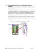
Dimensions 12 (305) 13.4 (339) 12.25 (311) 6.8 (172) 7.3 (185) 10 CFM Compressed Air Dryer Chapter 7: Appendix 15.
7-4 Spare Parts List Parts not included in this list must be replaced by the factory. Part No. Quantity Description 35452 1 Filter Regulator 725.00002.00 1 Fuse (110 volt) 725.00001.00 1 Fuse 220/1/50 725.00001.