SDRIOM-2 PN# 94.2000.03 P HVAC PRODUCTS 4830 TRANSPORT DRIVE, DALLAS,TX 75247 PHONE: 214-638-6010 FAX: 214-905-0806 www.sterlinghvac.com INSTALLATION, OPERATION AND MAINTENANCE MANUAL FOR SDR MODEL DIRECT GAS-FIRED HEATERS ATTENTION: READ THIS MANUAL AND ALL LABELS ATTACHED TO THE UNIT CAREFULLY BEFORE ATTEMPTING TO INSTALL, OPERATE OR SERVICE THIS UNIT! CHECK UNIT RATING PLATE FOR TYPE OF GAS AND ELECTRICAL SPECIFICATIONS AND MAKE CERTAIN THAT THESE AGREE WITH THOSE AT POINT OF INSTALLATION.
SECTION I - FORWARD I.As is the case with any fine piece of equipment, care must be taken to provide the proper attention to the operation and maintenance details of this machine. Table Of Contents Section I: Forward and Table of Contents........................ 2 Section II: General Information........................................... 2 Section III: Installation............................................................ 3 Section IV: Pre Start-Up........................................................
SECTION III - INSTALLATION This equipment must be installed and wired in accordance with regulations of the National Board of Fire Underwriters, National Electrical Code, and local governing bodies. The following recommendations are not intended to supplant any requirements of federal, state, or local codes having jurisdiction. Authorities having jurisdiction should be consulted before installations are made. Local codes may require additional safety controls and/or interlocks.
D. Electrical Connections DANGER: Never use an open flame to detect gas leaks. Explosive conditions may exist which would result in personal injury or death. WARNING: Open all disconnect switches and secure in that position before wiring unit. Failure to do so may result in personal injury or death from electrical shock. WARNING: To avoid equipment damage or possible personal injury, do not connect gas piping to this unit until a supply line pressure/leak test has been completed.
SECTION IV - PRE START-UP 6. Check set screws on all bearings, pulleys and fans for tightness. 7. Check voltage supplied to disconnect switch. The maximum voltage variation should not exceed ±10%. Phase voltage unbalance must not exceed 2%. 8. Check thermostat(s) for normal operation. 9. Check that system duct work is installed and free from obstructions. 10. Check that fans turn free in housing. 11. Check burner for proper location and alignment. 12.
SECTION V - UNIT START-UP Close or replace all doors and service panels. Unit will run for 5 seconds before ignition trial. Turn main disconnect switch off. Verify the incoming line voltage matches the unit nameplate rating. If the voltage is over ±10% of nameplate rating or phase voltage unbalance is over 2%, notify the contractor or power company. NOTE: 3 OR 4 TRIALS MAY BE NEEDED TO PURGE AIR FROM GAS LINE. United Technologies Electronic Controls Spark Ignitor Watch microammeter carefully.
When checking operation of air pressure switches on systems without pilot the heat switch will have to be turned off approximately five seconds to reset the ignition control. C. Gas Pressure Switches - Operate unit in Heat mode. The low pressure switch will trip out and must be reset before resuming operation when the inlet gas valve is turned off during operation.The high pressure switch may be checked out by reducing the setting of its trip point below unit operating pressure.
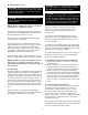
SECTION VII – TROUBLESHOOTING System without Pilot Symptom A. If blower does not operate. Cause 1. Low or no voltage. 2. Fuse(s) blown. 3. Customer interlock not closed or connected. 4. Fan Off-On switch in Off position. 5. Time clock, night setback thermostat or field installed controls open. 6. Freeze protection tripped. 7. Damper motor not operating, or its end switch not making. 8. Overload protection on motor starter tripped. 9. Belts loose or broken 10. Bearings seized. 11.
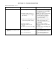
SECTION VII – TROUBLESHOOTING System without Pilot continued Symptom C. continued Cause Remedy 9. Defective gas valve or actuator. 9. Check power to gas valves. If gas pressure matches unit rating plate and valve does not open, replace gas valve or actuator. 10. Make sure spark rod is producing a sufficient spark to light off burner, make sure porcelain is not cracked. Check wiring or replace if necessary. 11. Make sure flame rod is in flame. Make sure porcelain is not cracked.
SECTION VII – TROUBLESHOOTING P-001004 P-001003 10
United Technologies Electronics Controls Operation of the Series 1016-400 Direct Spark Ignition Control On a call for heat a five second pre-purge is initiated. Upon completion of the pre-purge, the gas valve and 60 Hz spark are energized. When flame is detected, the control enters the steady state heating condition. Steady state heating will continue until the call for heat is satisfied. all outputs and enters lockout. Reset is accomplished by cycling the power off for a minimum of 5 seconds.
TROUBLESHOOTING GUIDE Series 14 Discharge Temperature Control continued Symptom E. Continuous High Fire (Electronics Problem). Possible Cause Field Test Remedy 1. Short circuit in TD114 Remote Temperature Selector circuit or wiring. 1. Inspect for shorts at or between Amplifier terminals 1 & 2 or TD114 terminals 1 & 3. 2. Check TS114/TS1007 for open internal circuit. Connect test resistor as described in Preliminary Circuit Analysis. Follow procedure outlined. 3. Inspect. 1.
TROUBLESHOOTING GUIDE Series 14 Discharge Temperature Control continued Symptom Reproduced with permission from Maxitrol® Company Possible Cause Field Test Remedy H. continued 4. Faulty Amplifier or erratic voltage supply. 4. With test resistor connected (per item H2) and TD114 locally connected (per item H3) turn TD114 selector dial through entire modulating range. Observe D.C. voltage across modulator terminals. 4. If erratic or unstable D.C.
TROUBLESHOOTING GUIDE Series 44 Room Temperature Control Symptom Reproduced with permission from Maxitrol® Company Field Test Possible Cause Remedy A. No Gas Flow. 1. Valve improperly installed. 1. Arrow on side of valve should point in direction of gas flow. B. Continuous Low Fire (Electronics OK). 1. Open circuit in modulator coil. 3. Ruptured main or balancing diaphragm. 1. Remove wires connected 1.
TROUBLESHOOTING GUIDE Series 44 Room Temperature Control continued Reproduced with permission from Maxitrol® Company Remedy Possible Cause Field Test E. continued 3. Incorrect space temperature calibration. 3. Follow procedures outlined in “Preliminary Circuit Analysis” in Section IX. 3. If proper action is obtained, first check item E2. Recalibrate if necessary. F. Incorrect Maximum or Minimum Discharge Air Temperature. 1. Improper TS144 location. 1.
TROUBLESHOOTING GUIDE Series 44 Room Temperature Control continued L. Incorrect Space Temperature 1. Incorrect maximum discharge air temperature setting (A1044). 2. Incorrect minimum discharge air temperature setting (A1044). 3. Insufficient burner capacity. 4. Incorrect space temperature calibration. Reproduced with permission from Maxitrol® Company 1. Check to see if heater is delivering air at maximum discharge air setting. 1.
1. Turn off gas supply. 2. Set thermostat or controller above room temperature to call for heat. 3. Watch for ignition spark or for glow at hot surface igniter either immediately or following prepurge. See IP module specifications. 4. Time the length of the spark operation. See the IP module specifications. 5. After the module locks out, open the manual gas cock and make sure no gas is flowing to the pilot or main burner.
B. Lubrication Instructions Item Manufacturer A slight showing of grease at the seals with accompanying normal bearing temperature indicates proper lubrication. Normal temperature can range from “cool” to “hot to the touch” depending on size, speed and surrounding conditions. Excessive bearing temperature indicates faulty lubrication. An insufficient amount of grease is suggested by a bearing showing no grease at the seals, and a higher than normal temperature and noise level.
D. Belt Tension and Adjustment Belt tension is adjusted during the initial run-in and test periods at the factory. However, the belts are run as slack as possible to prevent excessive damage to the bearings, yet tight enough to prevent slippage. It is necessary, therefore, to check belt tension during the first few months of operation, and to check for proper tension weekly during the first 60 days, after which 30-day check intervals are sufficient.
c. Put system back into operation and view burner while cycling through full firing range. This will give a visual check for blocked burner ports. Clean burner ports as necessary using a #47 drill. Burner plates should be cleaned with a wire brush at least once a year. 2. Inspect the flame rod and ignition electrode for dirt and moisture. Wipe off if necessary. Examine for any evidence of premature arcing. If in doubt, check continuity of flame rod to be sure it is not grounding out. Replace if required.
SECTION X - MAXITROL VALVE ADJUSTMENTS AND PRELIMINARY CIRCUIT ANALYSIS M411, 511, 611 Valve MR212 Valve High Fire Manifold Adjustments 1. Disconnect wires from amplifier terminal #4 (Series 14), or #2 and #4 (Series 44). This causes the valve to call for continuous high fire. 2. Adjust the pressure regulator to obtain the rating plate manifold pressure. 3. Reconnect the wires to amplifier terminal #4 (Series 14) or #2 and #4 (Series 44). High Fire Manifold Adjustments 1.
PRELIMINARY CIRCUIT ANALYSIS - SYSTEM 14 For ease in troubleshooting, it is advisable to wire the system as follows (this differs from the normal connection). The Discharge Air Sensor is disconnected and replaced with a 10,000 ohm,1/2 watt test resistor (terminals 3 and 4). If inlet air sensor is being used, disconnect and replace with a jumper.
Section 4 1. With proper voltages observed thus far and modulator responding correctly, wire the system (see Figure 1), except have TS144 connected in place of jumper. Set A1044 MIN temperature selector at least 10°F above outdoor temperature. Set A1044 MAX temperature selector at mid-range. Heater is now under control by TS144 Discharge Air Monitor. Figure 1 2. Turn Test-Potentiometer to maximum resistance. Delivered air temperature should be per A1044 MAX temperature setting.
1. 2. FOR CANADIAN INSTALLATIONS ONLY All installations must conform with local building codes, or, in the absence of local codes, with current CAN/CGA-B149Installation Codes For Gas Burning Appliances and Equipment. All electrical connections must be in accordance with Canadian Electrical Code, Part 1, CSA Standard C22.1. All electrical connections must conform to the current edition of the Canadian Electrical Code, Part 1 CSA Standard C22.1 and applicable local codes.