
Automobile Battery Charger User Manual


BATTERY CHARGER
12 Volts – 30 Amps (1230CED)
12 Volts – 40 Amps (1240CED)
12 Volts – 50 Amps (1250CED)
24 Volts – 25 Amps (2425CED)
ENGLISH
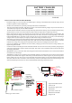
Battery
charger
Engine
start battery
Domestic system
Any other
battery bank
Fit battery
temperature
sensor to the
negative
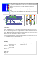
Battery type selector switch
Fused common negative
Positive outputs
1: open lead-acid & traction:
yellow L.E.D.
2: gel (Exide): green L.E.D.
3: gel (USA):
green L.E.D.– Flash 10x
4: Sealed acid & AGM:
orange L.E.D.
1
2
3
4
INSTALLATION OF THE BATTERY CHARGER
- Position the charger in a cool, dry and well ventilated space, ensuring a reasonable airflow around the charger. Do not
install in a cupboard or sealed compartment.
- Install as close to the batteries as possible, preferably within 2 meters of the batteries.
- This unit is fitted with an automatic 110V/230V crossover switch and the following voltages may be used: 80V-130V or
170V-280V at any frequency between 40Hz and 400Hz.
- The cable diameter should be 16mm² for 25Amps to 40Amps and 25mm² for 50Amps. If you install the unit further away
from the batteries you have to increase the thickness of the cables to compensate for voltage drops in the line.
- Before switching on the charger it is important to set up the battery type. Please choose a battery type from below. The
highest charge rate (and voltage) will be the open lead-acid (set to 14.8V (2425CED: 29.6V) on high charge), then sealed
lead-acid and AGM (14.4V (2425CED: 28.8V)), then gel (14.1V-14.4V (2425CED: 28.2V-28.8V)). (The AGM and gel
voltages tend to vary from company to company so check which voltage your batteries require).
- If the battery type requires to be reprogrammed, select the appropriate setting on the dip switches and ensure the charger
is switched off and on again for the settings to take effect. (This is because the internal software chip requires a re-boot to
install the new settings.) The settings have not taken effect if the L.E.D. has not changed to the correct colour.
- In the event of different types of batteries, the lowest battery voltage type must be selected. Never charge a battery on a
higher setting than it should.
- Connect the cables as in the diagram. Ensure that all the terminals are used. In the event of only one battery being charged,
connect the surplus positive output to another used output. This ensures correct regulation. Failure to do this will reduce
the charging performance.
- IMPORTANT: Always connect the cables to the charger first then run them to the batteries. Never connect to the batteries
first and then run to the charger.
- WARNING: The charger case is earthed as per international regulations. On most boats, the AC earth is connected to the
bonded system and then to the negative of the battery, this means that the case could be negative. If you touch the positive
battery cables to the case, then you can set up a dead short to the battery negative via the earth cable and melt the earth
cable; this could start a fire. To avoid this, ensure the battery connectors on the output studs do not touch the charger case
and use insulated output connectors. It is also recommended that all the charger outputs have a fuse.