
Marine Instruments User's Manual


Battery Temperature sensor: see fig 3 part c
This sensor is the same type and configuration as the alternator temperature sensor, however, it should be placed
on the battery terminal on one of the batteries in the domestic battery bank, as this is the battery bank most likely
to have the lower life expectancy. The idea behind temperature sensing is to monitor the battery temperature and
reduce the charger voltage as the battery temperature rises due to either high ambient temperature, excessive
installation in the battery box, or a battery failure. In the event of the first two then the output voltage of the
alternator will be reduced to prevent any unnecessary heat rise, however, in the event of a battery cell failing ad
the battery exceeding 50 deg c then a alarm will be transmitted to the remote panel(if used) and the L.E,D
number 5 (red) will flash on the local panel will come on. This is a fatal shutdown and can only be
overridden by switching the engine off and on again. Always find out the cause of this alarm condition, do
not simply reset the system and carry on regardless as this will cause excessive gassing and a possible fire
The same safety protocol is built into this system as above, if you do not wish to use this sensor, or in the
event of it becoming broken, then the software will pick up the fault and shut down its function and revert
to a safe 20 deg C default setting.
D+ disengage: see fig 3 part d.
Most alternators have a ignition warning light on there dash (the light which comes on when the ignition is
switched on and then the light switches off when the engine starts and the alternator starts to work). In the event
of the alternator failing in most circumstances the ignition warning light will come on warning the operator of a
fault with the alternator. Some modern alternators bring this feature a little further (the butec and some of the new
magnetic merellie alternators, less than 0.1% of alternators used) have a new feature, this is that in the event of
the standard alternators own regulator failing then it also switches on the igintion warning light to show a fault in
the system. The problem with this is that when a Advanced Alternator Regulator is used then the alternators
voltage is increased (by the Advanced Regulator) the standard regulator thinks it has failed and sends out the
signal. This makes the operator think there is a problem. The D+ circuit disengages the ignition warning light
after checking that everything is OK so although the standard regulator sends out the warning signal, the Sterling
system blocks its transmission to the dash and we take over the motoring. In the event of a fault we then
disengage and show any faults.
Alternator Temperature sensor see fig 3 part a
This sensor connects to the alternator and in the event of the alternator case or diode pack (depending on where it
is connected) exceeding 90 deg C then the Advanced Regulator will DISENGAGE (ie switch off the high charger
rate) until the alternator reduces its temperature to below 65 deg C, then the Advanced Regulator will re-engage
itself and continue, a warning will be displayed on the remote panel (if used) and a LED on the local display
(number 8) will illuminate while the system is disengaged.
Where to fit.
The best place to fit this sensor is to connect it by a jubilee clip directly to the exposed stator of the alternator if
possible however some modern alternators enclose the stator making access to the stator impossible, in that case
the best you can do is connected it to the main B+ terminal which is usual connected by a copper bolt direct to
the diode pack.
In a well ventilate engine room this feature is normally not required and was only added as a after though for
sailing boats in hot climates with heavy sound insulation. Always remember that this only disengages the
Advanced Regulator but cannot prevent your standard alternator’s own regulator from over heating the alternator
The temperature sensor is isolated and also has no polarity preference, ie the red and black cables do not donate
pos and neg.
The temperature sensor cables can be extended
Please note that in the interests of safety, (unlike other companies) if you do not wish to use any
temperature sensor or if one of the cables become broken or disconnected, the software program will
detect this within 2 seconds of the fault and default to the standard safe settings.
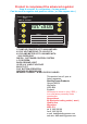
Display Mode 2: Flashing L.E.D. This indicates that the temperature sensor has picked up the battery
temperature exceeding 50 degrees C. This usually means that the battery is defective and on it’s way to
boiling. Check the voltage across the battery, if below 14 volts and 50 degrees C then the battery is defective.
Replace as soon as possible.
f:Tri Coloured L.E.D: This simply displays the battery type that the processor has been set to. All information
regarding this is on the label.
g:Red L.E.D Battery Negative Trip Fault: This alarm shows that there is a fault on the negative between the
battery negative and the alternator negative. This is usually due a bad connection. Please clean all
connections and check cable crimps etc.
h:Green High Alternator temperature disengage: This shows that the alternator temperature sensor has exceeded
90 degrees C and has automatically disengaged the Advanced Regulator. The regulator will automatically re-
engage at 65 degrees C. This process is fully automatic and requires no intervention. If you find this trip
working a lot of the time, I suggest you check your engine room cooling and I would recommend a fan
cooling system, blowing cold air from outside onto the back of the alternator (alternators suck air from the
back through themselves to the front).
i:Yellow 12 volt system setup: This shows the system is set to 12 volts, it cannot accidentally be set to 24 volts or
jump to 24V itself as an internal link must be made. Please ensure this is on if your system is 12 volts.
j:Green 24 volt System Setup: This indicates that the system is set up to 24 volts only. Under no circumstances
should the device be run in this mode if your system is 12 volts as all the trips will be set to 24 volts This will
result in the destruction of your batteries with no warning given.
The most common fault, this shows the alternators voltage has exceeded 17.5 (or 37 volts
in the case of 24 volts). This happens for various reasons such as cables from the alternator to the battery are
too long and not thick enough to carry the current or if there is an amp meter in the circuit then usually there
is a problem with the connections to the amp meter. If an installation has been running satisfactorily for a
period of a few weeks and this starts then check if the split charge relay or diode is OK and has not failed.
Please note that when this, or any trip light is on the Advanced Regulator has been electrically totally
isolated from the alternator and is no longer in use.
All L.E.D’s flashing:
If the alternator voltage continues to rise after this has
tripped then please check the alternators own regulator .and stop and disconnect the alternator