
Marine Instruments User's Manual


1) Isolate the alternator from the batteries (to prevent any accidents with live cables)
2) Remove all the wires from the back of the alternator (note down on this sheet as you go through the
instructions to ensure correct placement of the regulator set-up switches).
3) With all the cables removed, remove the alternator.
4) Not so bad? Now for the hard bit! We are trying to get to the two brushes, which supply the rotor its current;
they are usually connected to the regulator. Remove the regulator from the back of the alternator (usually 2 or 4
screws holding a component onto the back of the alternator) when this is removed the regulator should come
away with the brushes attached. This should be no problem for about 80% of you with Lucas, Bosch, Volvo,
however, the following things could be different:
a) A brushless alternator, most common S.E.V. Marshell 35 amp alternator fitted to old Volvo/Buch engines, has
special instructions. On the alternator regulator is an F or D/F connection, this is the field wire, i.e. where the
WHITE wire goes. This alternator is a positive alternator field control; therefore, change the booster setting from
negative to positive. (CONNECT THE BROWN WIRE TO THE D+/61 /L TERMINAL, THE REST AS PER
STANDARD. The best advice is to use this alternator as a sea anchor, and buy a decent size alternator, a 35 amp
high revving alternator is no use to anyone).
b) Remote regulators, some alternators have regulators fitted remotely and connected to the alternator via 3-5
small wires (usually on old alternators), advice: The wires are still connected to a brush box on the alternator,
remember it is the brushes we are after, locate the brushes as per normal.
c) Yanmar, Hitachi alternators require the alternator case to be split (unbolted, not hit with a sledgehammer),
this will reveal the brushes in the back part. Please note for reassembly the two small holes in the brush housing
which enable a wire to hold the brushes up when trying to reassemble the alternator.
5) Having found the brushes solder a 100mm length of 10 amp cable to the top of each brush.
Problems: Lucas regulator connectors are made from stainless steel, and as such normal pre-fluxed solder is no
use, use standard plumbers flux from a tub and the solder will stick with no problem.
6) Having connected a cable to each brush, reassemble the alternator and replace it on the engine.
Problems: Volvo engines with Valeo alternators require some cutting around the regulator seal. Use your common
sense never nip wires between the regulator and alternator case.
7) Ensure the ends of the two new cables are not touching each other, the alternator, or the engine, and reconnect
the alternator.
8) After the alternator is reconnected, run the engine as normal,
i.e. the ignition warning light on the dash should out when the alternator is charging as per normal.
9) This is the most important part. With the engine running well on tick over, using the voltmeter, we require
the voltage from both the cables you have just fitted to negative:
Cable 1 = ..............volts cable 2 =...............volts
(Also make a note of the alternators output voltage while doing these tests, if the alternator is working then we
would expect to see a voltage of between 13-14 volts, if below 13V then the alternator is not working, if above
14.5 then the alternators own regulator is defective or one or the wires you have connected have shorted to the
negative).
For Alternator Type:
If the voltage on any of the cables is between 2-12 volts and the other is 14 volts then this is a negative rotor
control, go to the pre installation section and write
If the voltage on any of the cables are 2-10 volts and the other is 0 (zero) volts, the alternator is a positive rotor
control, go to the pre installation section and write
(For reference only, 90% of alternators in Europe are negative, these include Bosch, Valeo (Volvo), Hitichi
(Yanmar), Lucas. The only positive alternators tend to be old alternators with remote regulators and American
alternators such as Motorola and AC Delco, (this information is to be used as a rough guide only)).
In either case, we keep the 2-10 volt cable and either remove or cut the 14 or 0 volt cable. (Ensure this cable
cannot touch the alternator case).
10) Having found the field wire and identified the alternator type the hard work is over, now to install the
Other special instructions relate to the very old Bosch mechanical regulator (about 25 years old), this must not be
used in conjunction with the Sterling Regulator, however, conduct the tests as above, you will find the alternator
is a positive field control. When the correct field wire is obtained set the Advanced Regulator to positive and
remove the old Bosch regulator this is not a common thing).
ensure the alternator is working as standard,
WARNING: GO NO FURTHER IF THE ALTERNATOR IS NOT WORKING. The alternator must be in
normal working mode before continuing i.e. giving out about 14 volts from the output of the alternator ( x 2
for 24V)
WARNING: GO NO FURTHER IF THE ALTERNATOR IS NOT WORKING. The alternator must be in
normal working mode before continuing i.e. giving out about 14 volts from the output of the alternator ( x 2
for 24V)
NEG
I will say again for people who thing I am joking!
POS
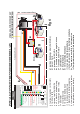
UNIVERSAL ADVANCED REGULATOR FITTING INSTRUCTIONS.
Thank you for purchasing the most advanced and powerful alternator regulator currently available in the world
today. Please do not underestimate the effect this device will have on a conventional charging system. It is
important to understand that your existing cables and layout may not be up to dealing with the extra performance
from the alternator but do not worry, the Advanced Regulator has many safety devices built in to protect your
system from damage in the event of the installation being unable to handle the extra performance caused by this
device. The software will pick up any problems and disengage the unit and give a warning.
PRE INSTALLATION:
This device is not difficult to install, if a logical, step-by-step approach is maintained. Please note: The
and should be used in event of any problems.
Some basic tools, a voltmeter and soldering equipment are required for installation.
Because the new regulator has been made to be totally flexible for all battery and alternator types it is important
for you to collect the following information about your system. This will enable you to set the Regulator
correctly and obtain the maximum results from the device.
Please obtain the following information about your system and fill in the space provided, if nothing else it is
about time you knew this information.
Alternator Type: There are two alternator types, negative and positive rotor field control. Do not worry at this
stage, which you have, but it is vital that you identify the correct one before connecting the advanced reg ; this
will be dealt with later.
My alternator type is:
Battery Type: There are four main battery types: all the settings for these 4 battery types are clearly marked on
the Advanced Regulator label. There is a lot of conflicting settings for gel and A.G.M. we have shown the setting
recommended by Exide ( the major gel manufacturers ) however there are other companies who disagree with
this in the U.S.A. so we have a setting for them also, its best to check with your supplier.
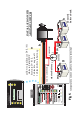
Battery Type selector ( fig 1 )
1) Conventional lead acid batteries, where you have access to the liquid level to maintain and top up the
batteries. These may be charged at a faster rate and as such, the high charge setting may be used. By far the fasted
charging batteries and the lowest cost. setting. Open lead acid/ traction batteries are the best type for fast charging
and long life.
batteries, not good for fast charging as cannot replace the water loss
associated with fast charging. as such the top voltage is reduced to reduce the water loss ,
3)Gel batteries ( Exide setting ) require , 14.4 volts 10-12 hrs on the charge voltage to charge them , as
recommended by Exide .
4) Gel / some
The new software in the digital regulator automatically calculates the battery bank size, charge state, and
alternator output, then using the internal DIGITAL processor sets the timing sequence every time you start the
engine.
INSTALLATION:
This is the only hard part, and this will also determine your alternator type, when you have identified the
alternator type please fill in the space above. Because there are so many alternators and many are not identifiable,
the installation instructions apply to all alternators.
To identify the field control wire: (do not panic about removing an alternator, they are simple devices).
DIGITAL
( see fig 3 code f ,
for the bridge position )
2) Sealed Lead acid and some A.G.M
A.G.M settings. Some gel companies in the U.S.A. recommend no more than 14.1 volts so we
have a setting for this. some A.G.M. batteries also require this setting.
This new unit is
suitable for 12 and 24 volt operation, obviously to set this unit up as 24 volt on a 12 volt system, would be
catastrophic and all effort is made to ensure this does not happen. The unit comes preset to 12 volt operation as
standard, a small electrical bridge must be made in order for the 24V function to be operated.
This bridge is not supplied in the regulator box but is Sellotaped to the centre of these
instructions ensuring that it cannot accidentally be installed. For 24V installation please fit the bridge as shown
on the diagram now !!.
(Neg or Pos).........................
Alternator Voltage (12 or 24 volt type).....................VOLTS
Alternator Current (35amp, 55amp etc)....................AMPS
Gel / sealed /A.G.M batteries are not recommended where fast charging is a priority. This is due to there limited
ability to absorb high charge currents fast effectively.
STERLING HELP LINE NUMBER IS UK 01905 26166
14.8 volts max for up to 8 hrs
14.4 volts max 4-6 hrs