
Installation Guide


Leg
1/32" (1 mm)
Cut Line
"B" Mark
B
Top Track
B
#8-18 x 1-1/2"
Screw Cover
Screw Cover
x2
x2
3
2
1
Notch
Rails
Long Leg
Outside of
the Shower
Wall Jamb – Top View
x2
Hanger
Bracket
Gasket
x2
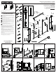
Tin Snips
9/64"
Miter Box
32 Teeth Per Inch Blade
Masking Tape
100% Silicone Sealant
Rubber Mallet
5/16" Masonry Bit for Tile
5/16"
1218520**
Hardware Skin Pack
1219162
End Cap
Screw
1048208-C
Wall Jamb*
Gasket
1213732
Barrel Nut
1050048-A
#8-32 x 3/8"
8-32 x 1/4"
Screw
1051142-A
Roller
1050047
Hanger Bracket
1219763-01**
Bolt
1077763-A
Left Door
Panel*
Wall Jamb*
Serial Number Label
1077762
Anchor
1218971
Bumper
1031943**
Screw Cover
1214505-01**
Top Track
1056868-A
Screw
1218476**
Center Guide
#8-18 x 1-1/2"
1213333-01**
Bottom Track
1219930-01**
Handle
Right Door
Panel*
Wipe
Seal*
1219002
Spacer
1216764-01**
Post
1216847**
Back Plate
Handle Skin Pack
1219473**
1219005-A
Screw
Bottom Wall
Jamb Notch
Bottom Wall
Jamb Notch
A
A
"A" Mark
Cut Line
1/4" (6 mm)
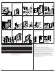
Measure distance “A.” Subtract 1/4” (6 mm) or
the width of a number 2 pencil from “A” and cut
the bottom track.
Position the bottom track on the center of the
ledge. If needed, file the ends to match the
corners.
Center the bottom track on the ledge with the leg
to the outside. Tape the bottom track in place and
mark the position.
IMPORTANT! The bottom track and wall jamb
must sit flat against the shower ledge and the
wall. If needed, trim and file the wall jamb. Use a
coin to match and to transfer the corner radius of
the shower to the wall jamb.
Position the wall jambs over the bottom track.
The long leg of each wall jamb faces the outside
of the shower. Plumb both wall jambs. Mark the
screw holes.
Remove the wall jambs. Drill 5/16” holes into the
walls and insert the anchors.
Reposition both wall jambs. Secure the wall
jambs with screws.
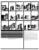
Measure distance “B” above the wall jambs.
Subtract 1/32” (1 mm) or the width of a saw
blade from “B.” Mark and cut the top track.
Place the top track over the wall jambs (either
side may face out). At each end of the top track,
insert and twist a bumper into place over the
rails. Slide the bumpers against the wall jambs.
For both doors, slide a gasket over the top of the
glass panel and into each mounting hole. Press
the hanger bracket over the gasket and align the
hanger brackets with the mounting holes.
5400 Heavy Glass Series Sliding Shower Doors
Sliding Shower DoorsSliding Bath Doors
11218556-2-D
USA/Canada: 1-800-STERLING (1-800-783-7546)
México: 001-877-680-1310
1218556-2-D
Installation and Care Instructions
Required Tools Parts Identifi cation
2 3 4
7 86 9
1 5
10
SterlingPlumbing.com
*Need help? Contact the STERLING Customer Care Center
at 1-800-STERLING (1-800-783-7546).
For service parts information, care and cleaning, and
other information, visit www.sterlingplumbing.com
**Finish/color code must be specifi ed when ordering.
Retain this document for future servicing.
Record model number from box for reference.
Model Number:______________
WARNING: Risk of serious injury. Damage prior to installation can
result in glass shattering. Inspect the glass and all parts for damage
before installation.
WARNING: Risk of serious injury. Improper installation can result
in glass shattering. Follow all installation instructions.
WARNING: Risk of serious injury. Do not cut tempered glass.
Tempered glass will shatter if cut.
WARNING: Risk of serious injury. Shower door and side panels
can shatter. Regularly inspect the glass and all parts for damage,
missing, or loose parts.
WARNING: Risk of serious injury. Always wear safety glasses
while cutting and drilling.
IMPORTANT! Do not touch the edges of the tempered glass with tools or
any other hard objects. Do not set the unframed tempered glass directly on
the floor or any hard surface.
IMPORTANT! Leave this manual for the end user.
Read these instructions before installing or using this product.
IMPORTANT! Do not cut the top track the same length as the bottom track.
NOTICE: The warranty does not apply to a product that has been modified
or altered in a manner other than as expressly permitted in the Installation
and Care Guide.
Walls must be within 3/8” (10 mm) of plumb.
Cover the drain with tape to avoid loss of small parts.
Follow the silicone sealant manufacturer’s instructions for application and
curing time.
To watch this installation video online, visit www.sterlingplumbing.com.
For care and cleaning and other information; visit
www.sterlingplumbing.com/care-and-cleaning.
Critical Information!
Read Before Installation!
Read and follow all instructions.