Model # Serial # ________________ ________________ serial numbers here _____________ _____________ for future reference ________________ ________________ ________________ ________________ ________________ ________________ ________________ ________________ ________________ ________________ ________________ ________________ ________________ ________________ ________________ ________________ Write down your Blender Sterling is committed to a continuing program of product improvement.
Table of Contents Table of Contents.........................................................................................3 Safety Considerations ..................................................................................5 Annex B Information ................................................................................ 7 1 General Information................................................................................8 1-1 1-2 1-3 1-4 1-5 1-6 1-7 1-8 1-9 Introduction ......................
Table of Contents 5 Operation ...........................................................................................47 5-1 5-2 5-3 5-4 5-5 5-6 5-7 5-8 5-9 6 Maintenance.........................................................................................79 6-1 6-2 6-3 6-4 6-5 6-6 6-7 7 SGB Blender Sequence of Operation .......................................... 47 Quick Start Procedure.................................................................. 47 Recipe Entry Formats.....................
Safety Considerations Sterling equipment is designed to provide safe and reliable operation when installed and operated within design specifications, following national and local safety codes. To avoid possible personal injury or equipment damage when installing, operating, or maintaining this equipment, use good judgment and follow these safe practices: ; Follow all SAFETY CODES. ; Wear SAFETY GLASSES and WORK GLOVES. ; Disconnect and/or lock out power before servicing or maintaining the blender.
Sterling “SGB-E” Series Blenders This blender is manufactured by ACS, Inc. at the ACS-Wood Dale facility: ACS, Inc. 801 AEC Drive Wood Dale, IL 60191 Phone: 630.595.1060 Fax: 630.595.
Annex B Information The following design information is provided for your reference: 1. 2. 3. 4. 5. 6. 7. 8. No modifications are allowed to this equipment that could alter the CE compliance Ambient temperature: 40 degrees Celsius – Maximum (104 degrees Fahrenheit) Humidity range: 50% relative humidity Altitude: Sea level Environment: Clean, dust-free and non-explosive Radiation: None Vibration: Minimal, i.e. machine mounting Special installation requirements: Clean, dry compressed air 1 cfm @ 60 psi (1.
1 General Information 1-1 Introduction We are pleased to supply Sterling auxiliary equipment for your facility. We manufacture a complete line of auxiliary equipment to satisfy all of your material handling, process cooling, scrap reclaim, size reduction, and automation requirements. Please feel free to contact your sales representative or our office if you have any questions.
1-5 Necessary Documents The documents listed below are necessary for proper installation, operation and maintenance of SGB Series Gravimetric Batch Blenders. You can obtain additional copies from the Service Department at Sterling or ACS Europe.
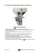
1-8 “SGB” Series Weigh Blender Mechanical Features SGB Slide Gate Blender • • • • • • • • • • Efficient Opti-Mixer® and “HC” mixer designs promote homogeneity Exclusive diamond design slide gate metering assemblies meter a large range for free flowing pellet materials Slide gate stroke limiting restrictors provided for accurate metering of minor ingredients Electro-polished 304 SS stainless steel weighing and blending components Precision 1/10% span accurate cantilever load cell weighing system Removable
1-9 “SGB” Series Weigh Blender with Mitsubishi TouchScreen Control Features • • • • • • • • • LCD touch-screen interface display operator control panel with 8’ cable Target vs. actual set point verification Inventory accumulation for all ingredients Audible and visual alarms Auxiliary alarm contact 50 recipe storage book Three (3) types of recipe entry procedures available: 9 Quick Set (up to 6-component) recipe entry. Color and additives are metered as a percentage of the virgin material.
1-10 SGB (-E) Series Specifications SGB Series Specifications Number of materials blended SGB-450 SGB-900 SGB-2500 4 Slide gate (adjustable, in (mm)) square SGB-4000 SGB-5000 2 to 6 2 (50) 2.5 (63) 2 to 5 3 (76) 4 (101) Supply hopper capacity, ft³ (l) 0.75 (21) 1 (28) 1.5 (42) 2 (56) Weigh hopper capacity ft³ (l) 0.12 (3.4) 0.4 (11) 0.65 (18) 1.4 (39) Typical batch size, lbs. (kg) 3 (1.3) 8 (3.6) 15 (6.8) 35 (16) Mixer capacity, lbs. (kg) 6 (2.7) 20 (9) 1/6 (.12) 30 (13.
1-11 Model SGB Blender System Component Description This section describes the various components of the blending system.
1-11-1 Material Supply Hoppers The material supply hoppers are located on top of the blender frame. These hoppers store a supply of material for the individual metering devices. They are sized based on the total throughput of the blender. The SGB blending system does not include any level indication devices on the unit. Optional low-level sensors are available.
1-11-2 Slide Gate Metering Assemblies Air operated slide gates are provided to meter the majority of pellet ingredients on the SGB blender. Important! The metering range assumes 1/8” diameter free-flowing plastic pellets weighing approximately 35 lbs./cu. ft. This is meant to be an approximate sizing recommendation and can vary with different bulk density resins, pellet configuration, etc. A stroke limiter (included) can be installed on the metering gates to limit their travel.
Each of the diamond gate air cylinders is actuated by a solenoid valve, which are controlled by the blender. When the solenoid valve is energized, it opens the metering valve cylinder. When the solenoid valve is de-energized, it closes the metering valve cylinder. If the power is interrupted to the blender, the metering valves will return to the closed position, to prevent material from over-filling the weigh hopper/mix chamber.
1-11-3 Weigh Hopper The weigh hopper on the SGB blender is used to weigh each batch of material, and includes an air-operated discharge valve. After the batch is weighed and the level sensor in the lower mix section is uncovered, the valve will open and discharge the batch into the mixer with the existing blended material. The discharge valve is also provided with a quick disconnect so the weigh hopper can be removed for cleaning.
1-11-4 Weigh Hopper Discharge Valve The weigh hopper discharge valve holds the material until it is dumped into the mixing section. The cylinder is actuated by a solenoid in the valve stack on the rear of the blender. In looking at the pneumatic circuit, you can see that the air regulator controls the flow of air to the valve stack.
1-11-5 Mix Chamber All of the Sterling batch blenders are equipped with an integral mix chamber. The mix chamber holds multiple batches of material so any variations in a batch are averaged over time. 1-11-5-1 Opti-Mixer™ The Opti-mixer™ is designed to provide bi-directional mixing action and can be easily taken apart for cleaning. This design is standard on all SGB blenders. 1-11-5-2 “HC” Mixer The “HC” Mixer features an open wheel design and is best used for multiple regrind materials and rigid pellets.
Typical Setup Screens Page 20 of 118 SGB Batch Blender with Mitsubishi Controller
Typical Operator Screens SGB Batch Blender with Mitsubishi Controller Page 21 of 118
Note: The touch-screen panel display on your unit may be slightly different than shown.
1-12 Pneumatic Slide Gate Below Mixer (Optional) The SGB blending system can be equipped with an optional pneumatic slide gate below the mixing chamber. The gate is used in applications when the blender is mounted above a large hopper, or for gaylord filling, etc. This gate holds the material in the mixing section, to ensure that it is properly mixed. Control of the mixer function is described below, and is determined by the position of the “knife gate switch” located on the side of the back control panel.
Supply Hoppers Pneumatic Slide Gate Below Mixer Blender Take-off Compartment Surge Bin Floor Stand Safety 2 2-1 Work Rules Install, operate, and maintain this equipment according to applicable work and safety codes for your location. This includes OSHA, CE, NEC, CSA, SPI, and many other local, national, and international regulations. Obey these specific work rules: Read and follow the instructions in this manual before installing, operating, or maintaining any equipment.
2-2 Tools and Equipment Needed You’ll need the following: • Hand tools • Fork lift or overhead lift • Wire, conduit, and fittings for wiring runs (if receptacle is not already in place) • Mounting bolts with nuts and washers • Compressed air tubing and fittings 2-3 Mechanical Installation Blenders may be mounted on the machine, a stand, or a mezzanine. Be sure it is securely attached and additional bracing is used if necessary.
The term IMPORTANT emphasizes areas where equipment damage could result, or provides additional information to make a step or procedure easier to understand. Disregarding information marked IMPORTANT would not be likely to cause personal injury. REPORTING A SAFETY DEFECT NOTE: If you believe that your equipment has a defect which could cause injury, you should immediately discontinue its use and inform Sterling, at our address listed in this manual. The principle factors which can result in injury are: 1.
continually reviewed, maintained, and improved. Keep minutes or a record of the meetings. Hold daily equipment inspections in addition to regular maintenance checks. You will keep your equipment safe for production and exhibit your commitment to safety. Please read and use this manual as a guide to equipment safety. This manual contains safety warnings throughout, specific to each function and point of operation.
before starting the unit. • At the beginning of your shift and after breaks, verify that the controls and other auxiliary equipment are functioning properly. • Keep all safety guards in place and in good repair. NEVER attempt to bypass, modify, or remove safety guards. Such alteration is not only unsafe, but will void the warranty on your equipment. • When changing control settings to perform a different mode of operation, be sure selector switches are correctly positioned.
When you need to perform maintenance or repair work on a blender above floor level, use a solid platform or a hydraulic elevator. If there is a permanently installed catwalk on your blender, use it. The work platform should have secure footing and a place for tools and parts. DO NOT climb on blenders, machines, or work from ladders. If you need to repair a large component, use appropriate handling equipment.
2-8-2 Safety Circuit Standards Safety circuits used in industrial systems protect the operator and maintenance personnel from dangerous energy. They also provide a means of locking out or isolating the energy for servicing equipment. Various agencies have contributed to the establishment of safety standards that apply to the design and the manufacture of automated equipment.
normal operation of the machine. Some of the safety devices utilize a manual activator. This is the method of initiating the safety lock out. This may be in the form of a plug, disconnect plug, lever or a handle. Within this lockable handle, there may be a location for a padlock. Personnel servicing the equipment should place a padlock in the lockout handle. WARNING! Always disconnect and lockout all electrical power and pneumatic (i.e.
Interlock Switch Electrical Disconnect Plug 2-9 Electric Safety Interlock Switch (All Models) A unique electric safety switch is used to shut off power to the blender any time the mixer door is opened. Do not tamper or alter with this switch in any way.
Electrical safety interlock switch (Located on mixer door) WARNING! Always disconnect and lockout all electrical power and pneumatic (i.e. compressed air) sources prior to servicing or cleaning any product, including all SGB Series blending systems. Failure to do so may result in serious injury or death. 3 Shipping Information 3-1 Unpacking and Inspection You should inspect your Sterling batch blender components for possible shipping damage.
3-2 In the Event of Shipping Damages Important! According to the contract terms and conditions of the Carrier, the responsibility of the Shipper ends at the time and place of shipment. The Carrier then assumes full responsibility of the shipment. ; Notify the transportation company’s local agent if you discover damage. ; Hold the damaged goods and packing material for the examining agent’s inspection. Do not return any goods to Sterling before the transportation company inspection and authorization.
Parcel Post Shipment ; Notify Sterling at once in writing, giving details of the loss or damage. This information is required for filing a claim with our insurance company. ; Hold the damaged goods with the container and packing materials for possible inspection by postal authorities. United Parcel Service Shipment ; Contact your local UPS office regarding damage and insurance claims. ; Retain the container and packing. ; Notify Sterling at once. 3-3 If the Shipment is Not Complete Check the packing list.
3-4 If the Shipment is Not Correct If the shipment is not what you ordered, contact Sterling immediately. For shipments in the United States and Canada, call 1 (800) 233-4819; for all other countries, call our international desk at 001 (630) 475-7491. Include the order number and item. Hold the items until you receive shipping instructions. 3-5 Returns Important! Do not return any damaged or incorrect items until you receive shipping instructions from Sterling.
Installation & Setup 4 4-1 Chapter Description and Objectives It is the intent of this chapter to familiarize the reader with the proper site requirements and installation procedures of the SGB blending system. The information in this chapter is NOT meant to replace or supersede an established local or company implemented procedures. It is meant to enhance them. 4-2 Site Requirements This section describes site requirements in detail.
Verify all clearances on the top and beside the processing machine. This is to insure that all motors, hoppers, control panels, etc. have adequate room for proper operation and servicing. Refer to the assembly drawing with the unit for actual height and width dimensions. Note: Allow at least 36” clearance around blender to provide adequate room for cleaning, servicing, etc. Using proper lifting equipment, lift the blender, using the lifting lugs attached to the top plate of the blender.
4-2-1-2 Mezzanine Mount In a mezzanine mount application, review the following items before installation begins. First, verify the SGB mounting locations match the mezzanine supports. Verify that the mezzanine is capable of supporting the blender with a full load of material and vacuum loading equipment installed. Important! While in operation, the SGB applies horizontal and vertical pressures to the mounting flange.
4-2-1-3 Floor Mount (Central Blender) In a floor mounting application, ensure adequate clearance for all blender operations and maintenance. The operator and maintenance personnel must have access to parts of the blender. If necessary, it is the customer’s responsibility to provide adequate, safe work platforms around the blender to meet state and local safety codes. Using proper lifting equipment, lift the SGB in place. Important! The blender must be securely fastened to the floor before operating.
4-3 Installation Overview This section will familiarize the reader with commonly used procedures for blender installation. After reading this chapter, the reader will be familiar with the installation requirements for all SGB blenders. 4-4 Mechanical Installation The installation procedure should be used as a general guideline for the proper installation steps required to install the SGB blending system. 1. Remove crate from around blender. 2. Secure strap of proper lifting capacity to both lifting lugs.
assemblies. 4-5 Electrical Installation The standard Sterling SGB blending system is designed to operate on 120/1/60 supply voltage (220/1/50 CE models are also available). The current requirements vary with the blender’s size and throughput rating. For exact current requirements, check the blender serial number tag, located on the rear plate of the mixer section. If a step down transformer was provided, it should never be used to power anything other than the blender. Loading equipment, etc.
4-6 Pneumatic Installation The SGB blending system uses plant-supplied compressed air to operate the metering and dump valves on the blender. CLEAN AND DRY air must be supplied to the blender. The air supply should be filtered through a 5 micron air filter with a water separator. Oil should not be used unless air dryers are installed on the compressed air supply. In this situation, an oiler may be required on the blender to keep the air cylinder seals lubricated.
SGB blending system. 4-7-2 Weigh Hopper Installation Remove the weigh hopper from the shipping box and install it in the blender on the load cell brackets. Connect the airline and close the mixer door, securing the latch. 4-7-3 Load Cell Adjustment The mechanical setup of the SGB blending system involves the adjustment of the weigh hopper load cells (Please refer to the figure on the next page). This figure illustrates the proper adjustment of the load cell mechanical stop bolt.
4-7-4 Final Setup 1. Connect the blender to the appropriate power source. 2. Connect the compressed air piping, ensuring that a 5-micron air filter is installed, along with the proper water trap, and lubrication unit, if required. Verify that 60 psi (4.14 bar) of clean, dry compressed air is supplied to the blender.
4. The screen shown below allows the operator to control the blender. The blender can be started or stopped and the recipe values can be changed. Other data shown on this screen consists of the mixer status, recipe status, and feeder type data. The Recipe Screen should startup in the “Quick Set” mode. If so, enter a valid recipe.
Operation 5 5-1 SGB Blender Sequence of Operation 1. Blender is started by turning system on or material dropping below level switch in mix chamber. 2. Metering gates are opened to meter material into the weigh hopper in the programmed order. 3. Each component is weighed then the batch is dumped into the mix chamber (provided the mixer “High level” switch is not covered). 4. The material is mixed in the mix chamber and flows into the processing machine. 5.
Recipes can also be changed while the blender is running. The new accepted recipe is entered at the beginning of the next batch. This allows the operator to modify the new recipe without affecting the blender until they hit the “Accept New Recipe” button. OR 4. The operator can load a previously stored recipe from the Recipe Book. The Recipe book also allows the operators to save the current running recipe.
the blender and the operator is not required to enter it. The ingredient names selected will be displayed on the run mode display so the operator will know what material is being blended. Important! The #1 hopper (“NAT” - Virgin Material) recipe ingredient will not be shown on the recipe setup menu. ADD (Additive) designations will weigh the ingredient as a percentage of natural material only. RGD (Regrind) designations will weigh the ingredient as a percentage of the total batch.
The preset part will be divided by the total of all parts, with each part representing the calculated weight for ratio control. Example of a 5-component Blend in “Parts” Mode Feeder Tag Virgin Regrind Color Additive Total: 5-3-4 Preset Part #1 #2 #3 #4 7,200 2,000 500 300 10,000 Calculated Weight (Ratio Control) 7,200/10,000 2,000/10,000 500/10,000 300/10,000 Switching Modes Recipe Modes can be switched while the blender is making a batch.
5-4 SGB Series Control System Menu Structure “Recipe” Page (Start) ¾ ¾ ¾ ¾ ¾ ¾ ¾ Change Recipe Values by touching the number you wish to change Touch “Accept New Recipe” button after you’ve made the desired changes Start or stop the blender by touching the “Push to Start” or “Stop” button Access “Recipe Book” Page Access “Clean Out” Page Access “Inventory Page” Access “Setup” Page “Recipe Book” Page ¾ ¾ ¾ ¾ ¾ ¾ Save the running recipe to the book Delete a stored recipe Load a stored recipe Erase all sto
5-5 Blender Calibration *NOTE: It is not necessary to calibrate the weight scale on a brand new blender, although it is recommended that the calibration be checked periodically to ensure that the reported inventory totals are accurate. Remember that in most cases a bad calibration is worse than no calibration. 5-5-1 Standard Calibration on a blender equipped with an OptiMix style mixer (Recommended only if the calibration is out of spec) 1. 2. 3. 4. 5. 6. 7.
3. 4. 5. 6. 7. 8. 9. 10. 11. 12. time the mixer will mix or the batch is dumped. Enter a “Mixing Time” by pressing the number next to “sec”, this is the amount of time to run the mixer after a batch is dumped into the mixing chamber. Remember that if the mix time is too long you may get material separation. Press the number next to “sec” on the “Remix Time” to set “Remix” off time. This allows the mixer to come on between batches if the blender cycle time is very slow, i.e.
5-5-4 Verifying Calibration (Recommended on a periodic basis to ensure accuracy) 1. 2. 3. 4. 5. 6. 7. 8. Login by touching “login” from the Inventory Page and enter “5413”, then touch the Sterling logo to access setup. Touch “Calibration” and then “Direct Scale Readout”. Remove the weigh hopper. Locate the weight display for each of the two load cells, directly below “Current Bits.” Write down the displayed value.
Inventory Shutdown: This feature allows the blender to make a certain amount of material at a time. If this feature is set to “0” then the feature will be disabled. If this option is used, the blender will make the set amount of material and will then shutdown and wait for the operator to restart the blender. This feature is useful when filling gaylord boxes. You no longer have to be troubled by a proximity switch that hangs in the box to sense when it is full.
**Note: The blender monitors the operator’s entries and determines if the recipe is valid before accepting the new recipe. If there is an error (such as the recipe does not add up to 100% and the blender is in Percentage Mode.) then a message is shown on the Recipe screen to alert the operator of the problem. The “Accept New Recipe” button is only shown if the recipe is valid and different from what is currently running on the blender. Recipes can also be changed while the blender is running.
the blender where there are moving parts. 4. Remove the weigh hopper by unplugging the air line disconnect fitting, holding the dump valve closed, lifting the hopper to clear the load cell brackets, and gently pulling the weigh hopper out of the blender. Important! To reduce the chance for damage to delicate load cells, use care when lifting the weigh hopper off load cell locating tabs and when reinstalling the weigh hopper on load cell brackets. 5.
5-8 Additional Operation Features 5-8-1 Display Description (LCD) The SGB blending system utilizes a standardized menu format. Each screen was designed to be user-friendly and provide the operator with the necessary information to run the blender. A typical menu is shown in the figure above.
5-8-2 Weigh Hopper (Load Cell) Calibration on blenders equipped with an OptiMix mixer Enter the Setup menu as described previously. See Section 5-3 for menu tree. The factory pre-calibrates the weigh hopper on the SGB blenders. Button #3 on the Setup Menu is “Calibration”. Press it to enter the screen (shown below) which will prompt you to enter the Calibration area. Press the button marked “Scale Calibration” to enter the scale calibration menu. Go Back to Setup Directory 1.
5-8-3 Mix Timer The mix timer is the amount of time that the mix motor will mix the material after it has entered the mixing section of the SGB blender. The timer has a range of 1 to 999 seconds. To set the value of the mix timer, the user must gain access to the Setup Menu. After entering the Setup menu, the user must select “Mixer and Dump Setup.
mix cycle after each dump of the weigh hopper. To view and change the value of the re-mix timer, refer to the “Mixer and Dump Setup” menu. All current values for Mixing and Remixing Times will be shown on this screen. The re-mix timer default value is factory preset at zero.
and Dump Setup” screen, and then select “Dump Delay”. The default time is factory set at zero seconds. This delay time is used to start the mixer prior to dumping the material from the weigh hopper into the mix chamber of the blender. 5-8-8 Weigh Hopper Dump Cycle The dump cycle allows the weigh hopper dump valve to cycle, or open and close, a number of times prior to commencing with the next batch cycle. The setting allows from 1 to 9 dump cycles between batches (open and closed cycles).
3.) Select a feeder (1-6) by touching the “Select Feeder” box. 4.) The current settings for the hopper that you have chosen will now be shown on the screen. 5.) Make the necessary adjustments to the “Stop/Continue if “Out of Material,” Alarm/No Alarm on “Out of Material,” and Out of Material Alarm Silence Delay (0-60 seconds) settings.” Once the settings for these features have been set on the displayed feeder, select a new feeder to configure as desired. 6.
• Calibration Error, Clean out hopper and check calibration: This alarm indicates that the maximum empty weight for the weigh hopper has been exceeded. The blender will automatically tare up to 0.25 lbs of material, but if this weight is exceeded, then an alarm will appear. This alarm is most commonly caused by a build up of sticky material in the weigh hopper and can be corrected by simply cleaning out the weigh hopper.
• E-Stop Screen: The blender is equipped with an E-stop switch that removes the power from all mechanical outputs. The E-Stop Screen appears along with an audible alarm whenever the E-Stop is activated. The operator can not access any screens until E-Stop is deactivated. The Panel View will then put the screen back to the display that the operator was on prior to hitting the E-Stop.
This screen will allow you to Open or Close the Feeder, Weigh Hopper, Mixer Knife Gate, Empty the Entire Blender, Start or Stop the Mixer Motor, Test the Alarm Output, Find out the Mixer Proximity Status and monitor the Current Hopper Weight.
the mixer section of the blender. If the dump delay is set, the mixer will start before the weigh hopper dump will open for the selected time. The blender will sit at rest until the high-level sensor in the mixing chamber is uncovered to start another weigh cycle. (Unless the Re-Mix timer is set to a value other than 0 and times out to restart the mixer to run for another mix cycle.) The level sensor is located on the back wall of the mixer chamber.
Blender Maximum Rate Average Batch Time Inventory Totals Go to Recipe Page Clear the inventory totals Accumulated Number of Batches Material Usage Rate This display indicates the amount of material in pounds that has been used by each feeder of the recipe. It is important to note that the weights are rounded off to the closest pound. On minor ingredients, several cycles may have to occur to show an inventory number.
• Recipe Book Page • Recipe Format Upon Start Up, the blender controller will default to the “Recipe Menu” screen. The “Recipe Book” screen can be accessed in the “Recipe Page” and is useful in storing and retrieving recipes. The Recipe format option can be accessed in the Setup screen and is used to select one of three available formats: “Quick Set”, Percentage Mode or Parts Mode. (“Quick Set” is the default setting preset at the factory.
can be scrolled to read “NAT” (natural), “RGD” (regrind), or “ADD” (additive). The selected label will be displayed for the ingredient hopper with an arrow next to the abbreviation. Component #3 is designed to handle regrind and most models come equipped with a larger, square gate to reduce the likelihood of bridging. If regrind is being used, it should always be run through component #3. If you don’t have regrind, another major ingredient can be run through component #3.
Example calculations of a five (5) -component blend in “Quick Set” Virgin (NAT): Additive1 (ADD): Regrind (RGD): Additive2 (ADD): Additive3 (ADD): ??? 5.00% - of virgin component 30.00% - of total batch 2.00% - of virgin component 1.00% - of virgin component Batch Size: 10.00 lbs. Total available: Regrind: 100.00% 30.00% Balance: 70.00% Virgin + Additive 1 + Additive 2 + Additive 3 = 70.00% Virgin + (5% of virgin) + (2% of virgin) + (1% of virgin) = 70.
Typical Batch Size SGB-450 SGB-900 SGB-2500/4000/5000 3 lbs. 8 lbs. 35 lbs. 5-8-17 Batch Size Menu The SGB blending system is a gravimetric batching system. The blender will weigh a preprogrammed batch of material each cycle. This batch size is determined by the blender’s weigh hopper size, the current recipe, and the bulk density of the ingredients.
When the Inventory Shutdown value is reached, the blender will finish the current batch of material. It will then stop and display to the operator that the inventory value has been reached. Additionally, it will flash an alarm and wait for operator attention.
Always verify that the Current Recipe is showing what you want to run, and that the correct recipe has been downloaded from the book.
5-8-19-2 Load a Saved Recipe from the Book The load from book function allows the operator to retrieve a previously stored recipe from the recipe book and install it into the current recipe menu. This will overwrite the current recipe, so make sure that it has been saved to the book before installing a new recipe in its place. To load a previously stored recipe from the Recipe Book: 1. 2. 3. 4. Note: Enter the Recipe Book by touching the Recipe Book icon located on the Recipe Screen.
5-8-20 Controller Features 5-8-20-1 Display Time and Date The display Time and Date item in the upper right corner of the “F940 Config” menu is used to verify the current time and date information. 5-8-20-2 Setting Date & Time The Set Date & Time feature is located in the “Panel View Config” menu of the Setup Screen. This feature allows the operator to set the SGB’s internal time clock and date. The clock data must be entered in the traditional Hours, Minutes, and seconds.
5-9 Stroke Limiters for Metering Gates Stroke limiters are supplied on components 1 through 4 with all SGB blenders to allow standard metering gates to meter small amounts of low percentage additive materials. Generally, the stroke limiter (Item 30) is not required on major ingredients (usually number 1 and 3) and should be removed. If they are left in place, throughput of the blender will be reduced.
Maintenance 6 6-1 Work Rules The installation, operation, and maintenance of this equipment must follow all applicable work and safety codes for the location where it is used. This may include, but is not limited to, OSHA, CSA, NEC, SPI, and other local, national, and international regulations. In addition, you must observe the following specific rules: ; Read and follow these instructions when installing, operating, and maintaining your equipment.
6-3 Controller Setup This section describes the proper setup of the SGB blending system control parameters. These parameters are operator changeable; however, these items should only require setup during the initial installation. Only authorized personnel should change them. For security reasons, the menu that is used to access these parameters is password protected. Many of the variables and setup parameters have been preset at the factory and do not need to be changed.
6-4 SGB Series Blender Menu Structure “Recipe” Page (Start) ¾ ¾ ¾ ¾ ¾ ¾ ¾ Change Recipe Values by touching the number you wish to change Touch “Accept New Recipe” button after you’ve made the desired changes Start or stop the blender by touching the “Push to Start” or “Stop” button Access “Recipe Book” Page Access “Clean Out” Page Access “Inventory Page” Access “Setup” Page “Recipe Book” Page ¾ ¾ ¾ ¾ ¾ Save the running recipe to the book Delete a stored recipe Load a stored recipe Erase all stored recip
6-5 Mechanical The mechanical design of the blender is very simple and very little maintenance is required. The only moving parts are the metering gates, weigh hopper dump valve and mixer agitator. The following maintenance is suggested: Daily • Inspect blender for any loose parts-tighten them immediately. • Verify quality of compressed air supply. • Verify mixer door is properly latched. Weekly • Inspect metering gates for proper operation.
6-6 Electrical 6-6-1 Description and Objectives This section is designed to give the operator an overview of the electrical system that controls the SGB blending system. Since the SGB’s control panel is a self-contained pluggable item, seldom will a maintenance person be required to enter the control panel.
6-6-4 Output Signals from Programmable Controller The SGB blending system uses several output control signals to control the process. All of these are very similar in nature, the first of which is the mixer motor control. The mixer motor is controlled by a PLC output. The weigh hopper dump valve output functions similar to the mix motor output. Please refer back to the wiring diagram. The origin of the weigh hopper dump signal is a PLC output.
6-7 Pneumatic System Maintenance The SGB blending system uses plant-supplied compressed air to operate the metering and dump valves on the blender. It is the user’s responsibility to provide CLEAN AND DRY air for the blender to be connected to. The air supply should be filtered through a 5 micron air filter and have a water separator installed. Oil should not be used unless air dryers are installed on the compressed air supply.
7 Troubleshooting 7-1 Description and Objectives This section provides basic troubleshooting procedures to common SGB blending system problems. Any problem encountered that is not listed should be discussed with an Sterling service technician. Problem Nothing happens when I push “Start Blender” Possible solution Check to make sure that air is hooked up and the regulator gauge reads at precisely 60 PSI. Check that the access door to the mixer is shut properly. Look on the Recipe Screen.
Problem Possible solution Weigh hopper occasionally overfills. Check batch weight setting in the recipe menu. See the setup chapter for more information. Check the load cells and weigh hopper mounting for binding, etc. Check to see that a pellet has not lodged under a load cell. Check the ingredient supply hoppers to verify proper ventilation.
Problem Mixer won’t shut off and runs continuously. Out of Material Alarm is displayed, but there is material in the hopper. I’m not getting Out of Material Alarms Calibration Weight Exceeded The feeder calibration values are moving too much. I can’t calibrate the Scale without an error message. I can’t calibrate the feeder without an error message. Possible solution Check the Mixer and Dump Setup to see if the mixer is configured for “Continuous Mixing”. Set it to “Timed Mixing”.
Weigh hopper does not empty completely. Check the dump time setting. It may be set too short. If this does not correct the problem, clean the weigh hopper and recheck the scale diagnostics readout. If not showing (0) zero when empty, recalibrate the scale. Problem Blender does not make rate. I have changed the recipe entry mode, batch size, inventory shutdown or feeder type and alarm flags, but the change hasn’t taken place. A feeder always puts too much material in the batch.
8 Blender Options The following is a list of options, which your blender may have been equipped with: Regrind Auger Metering (RAM) Used for feeding difficult regrind materials. Low Level Sensors Detects material supply problems before blender runs out. Remote Touch Screen Interface Allows control of blender from a second location up to 50 feet (30 meters) away. Mezzanine & Floor Stands Supports blenders in mezzanine mount and freestanding applications.
Spare Parts 9 9-1 Spare Parts List SGB Series Gravimetric Batch Blending Systems 9 Please see Section 9-2 for parts identification and exploded views. Model SGB-450 Part No. 53292 Description Air Cylinder (weigh hopper dump) 53272 2kg Load Cell 10220 Mixer Agitator (Opti-Mixer) A0556548 Mixer High Level Sensor 35448 Slidegate Air Cylinder (3” stroke) A0565882 Calex Module A0569702 PLC A0569708 SBG Graphics Panel A0542200 1.5 Amp Fuse A0542207 3.
A0565882 Calex Module A0569702 PLC A0569708 SGB Graphics Panel A0542200 1.5 Amp Fuse A0542207 3.0 Amp Fuse A0569108 Calibration Weight (~25 lbs.) 9-2 Model SGB Blender System Component Description This section describes the various components of the blending system.
9-2-2 Typical Mixer Section (Front) Typical Opti-Mixer™ - Front Assembly Detail Page 92 of 118 SGB Batch Blender with Mitsubishi Controller
01 02 03 04 05 06 07 08 09 Nameplate and indicator mounting plate Nameplate Upper polycarbonate Opti-Mixer™ door Door clamp “Caution” label Lower stainless steel Opti-Mixer™ door Mixer agitator door bushing Door hinge Door hinge base 9-2-3 Typical Mixer Section (Rear) Typical Opti-Mixer™ - Rear Assembly Detail SGB Batch Blender with Mitsubishi Controller Page 93 of 118
10 11 12 13 14 15 16 17 Opti-Mixer™ back plate Cover plate Back control panel Cover plate Proximity sensor (Mixer “high” level) Mixer proximity sensor mounting plate Mixer gear motor Mixer agitator shaft coupling 9-2-4 Typical Mixer Frame Page 94 of 118 SGB Batch Blender with Mitsubishi Controller
Typical Opti-Mixer™ Frame Assembly 18 19 20 21 22 23 24 25 Hinge mounting bracket Mixer door clamp Load cell cover Opti-Mixer™ top plate Opti-Mixer™ frame Warning label Opti-Mixer™ frame side panel Hinge mounting bracket SGB Batch Blender with Mitsubishi Controller Page 95 of 118
9-2-5 Typical Gate Assembly Typical SGB Series Diamond Gate Assembly Detail 28 29 30 31 32 33 34 35 36 37 38 Slide gate guide rod Stainless steel gate assembly base Slide gate stop (stroke-limiter) Retaining clip Slide gate air cylinder Slide gate air cylinder pneumatic connector fitting Slide gate air cylinder pneumatic barb fitting Slide gate assembly material chute (deflector) Notice (warning) label Pin Diamond v-gate (metering slide gate) 9-2-6 Typical Supply Hopper Page 96 of 118 SGB Batch Blender
Typical SGB-450 Series Hopper Assembly Detail 40 41 42 43 44 45 46 47 48 49 50 51 Mild steel hopper cover Hopper insert (square to diamond-polyurethane) Mild steel hopper Gasketing Polycarbonate access door N/A Polycarbonate hopper sight glass Blow-off tool holder Blow-off tool Drain plug Cleanout door clamp Optional low level proximity sensor mount 9-2-7 Typical Weigh Hopper SGB Batch Blender with Mitsubishi Controller Page 97 of 118
Typical Weigh Hopper & Load Cell Detail 52 53 54 55 56 57 58 59 60 61 62 63 Page 98 of 118 Left weigh hopper bracket Inside mixer plate Weigh Hopper Weigh hopper discharge air cylinder pneumatic connector Weigh hopper discharge air cylinder Weigh hopper discharge air cylinder mounting bracket Weigh hopper discharge hinge pin (bolt) Weigh hopper discharge flapper Right weigh hopper bracket Spacer Load cell(s) Load cell mounting plate SGB Batch Blender with Mitsubishi Controller
Technical Assistance Parts Department Call toll-free 7am–5pm CST [800] 783-7835 or call [262] 641-8600, Fax [262] 641-8653 The ACS Customer Service Group will provide your company with genuine OEM quality parts manufactured to engineering design specifications, which will maximize your equipment’s performance and efficiency. To assist in expediting your phone or fax order, please have the model and serial number of your unit when you contact us.
10-2 Returned Material Policy 10-2-1 Credit Returns 1. Prior to the return of any material authorization must be given by Sterling. A RMA number will be assigned for the equipment to be returned. 2. Reason for requesting the return must be given. 3. ALL returned material purchased from Sterling returned is subject to 15% ($75.00 minimum) restocking charge. 4. ALL returns are to be shipped prepaid. 5. The invoice number and date or purchase order number and date must be supplied. 6.
10-3 Warranty Sterling warrants all equipment manufactured by it to be free from defects in workmanship and material when used under recommended conditions. The Company’s obligation is limited to repair or replace FOB the factory any parts that are returned prepaid within one year of equipment shipment to the original purchaser, and which, in the Company’s opinion, are defective. Any replacement part assumes the unused portion of this warranty.
Safety Tag Information 11 11-1 SGB Blender Safety Tags Pinch Point Slide Gate Read Operation and Installation Manual Shear Point Rotating Mixer Earth Ground High Voltage Inside Enclosure PE Protected Earth Ground Shear Hazard Rotating Auger Lifting Point Page 102 of 118 Controller SGB Batch Blender with Mitsubishi
11-2 Pushbutton and Touchscreen Tags Button Function Turns power on to the blender controller. (Found on back of controller.) Power On Turns power off to the blender controller. (Found on back of controller.) Power Off Stops blender & re-starts controller. Press to move back one screen level in controller function. Move forward one screen level in controller function. Start (or stop) blender with current program parameters. Can erase current settings for one recipe or all recipes.
11-3 Blender Identification (Serial Number) Tag (Located on back of mixing chamber) SGB Series Blender Model Number SGB-900 Max Blend Capacity 318 KG/HR 220V Serial Number 060701R 1Ǿ Date of Manufacture 06/2002 4.5A Over-current Protection Device (s) 4.5A Total Frequency 50/60Hz Compressed air supply 4.14 bar (60 psi) Mixer Speed 16 RPM Blender Mass 400 lbs/(180 KG) Electrical Diagrams & Pneumatic Diagram 5200 W.
12 Appendix Important! Hidden, programmable features and hidden menu pages should not be made available to floor operators. These pages include the Service Supervisor Information addendum located in this section. Unauthorized changes to these factory settings by inexperienced operators may prevent the SGB unit from operating properly, and may void part or all of the warranty.
12-1-2 Factory Setup Menu Available Selections Metering Test Screen This screen is useful in both R & D and development purposes when testing the metering performance of each feeder. The user can perform a “Single Meter by Weight” to evaluate the mechanical standard deviation of the gate or auger. This test meters for the calculated time based off the target weight entered on this screen.
introduced material into the weigh hopper, adjust the Maximum Empty Weight of the hopper. The weight filter is the specialized filter algorithm that smoothes erroneous load cell readings. The signal will be filtered more if this value is increased and less if decreased. This setting should not be modified except by the developer except under unusual circumstances. Adjust the limit for “Hopper Over Max Weight” Weight Filter Weight/Sec.
Feed Calibration Options Screen This screen allows you to perform the feeder calibrations for each feeder (in weight per second). This is useful when the feed calibration is giving you an error message (most commonly caused by overfilling the hopper during the calibration). Select a feeder and then follow instructions. An error is shown if the current feeder calibration feed time was too short, the feed time was too long, or if the hopper weight exceeded 110% of the set batch weight.
Feeder Setup This screen allows you to modify the type of each feeder. In most cases, the user will want to keep regrind on hopper 3 because that blender has been specifically designed to handle the regrind. These settings should only be modified under special circumstances. If the blender is configured in “Quick Set” then one hopper must be configured for Regrind and only one hopper must be configured for Virgin material. If this is incorrect, a message will be given on the Recipe Screen.
box. 2. The current settings for that hopper will be shown. 3. Make the necessary adjustments and select a new feeder to configure if desired. 4. Hit “Done” to exit. Select a Feeder to Configure Enable or Disable Retries Enable or Disable Alarms Go back to Setup Directory Change the Alarm Silence Delay Alarm Log This screen shows the last 100 stored alarms. The log can be viewed and cleared.
Information included in this manual is subject to change without notice.
12-2 Passwords User Password Maintenance Password CAUTION! “5413” “3145348” Maintenance password should only be supplied to qualified personnel! The program can be compromised. 12-3 Default Values (factory defaults shown): SGB BLENDER CONFIGURATION PARAMETERS Model Number/Type SGB-450 SGB-900 SGB-2500 SGB-4000 SGB-5000 RECIPE FORMAT Recipe Entry Mode Batch Size Inventory Shutdown Batch Ready Mode AutoStart Mode QUICK SET 3.
Dump Delay Dump Cycles Mixer Dump Time Continuous/Timed Mixing 0 2 4 1 6 5 TIMED USER PASSWORD 5413 3145348 User Password Maintenance Password SGB BLENDER CONFIGURATION PARAMETERS Cont’d.
Hop6 Allowed Underfeed 5 Double Gate Threshold Out of Material Retry limit before alarm Batches for process rate Process Rate Filter 10 3 SGB BLENDER CONFIGURATION PARAMETERS Cont’d.
Service Notes SGB Batch Blender with Mitsubishi Controller Page 115 of 118
Service Notes Page 116 of 118 Controller SGB Batch Blender with Mitsubishi
Service Notes SGB Batch Blender with Mitsubishi Controller Page 117 of 118
Page 118 of 118 Controller SGB Batch Blender with Mitsubishi