$3000 Operation and Installation Manual SMD Series Dehumidifying Dryers Important! Read Carefully Before Attempting to Install or Operate Equipment Part No. A0570029 Revision NEW Bulletin No.
Write down your dehumidifying ________________ ________________ dryer serial numbers ________________ ________________ here for future reference ________________ ________________ ________________ ________________ Performance figures stated in this manual are based on a standard atmosphere of 59°F (15°C) at 29.92” Hg (1,014 millibars) at sea level, using 60 hz power. Altitude is an important consideration when specifying dehumidifying dryers.
Table of Contents 1 General Information ............................................................ 9 1-1 1-2 1-3 1-4 1-5 1-6 1-7 2 Safety.................................................................................. 14 2-1 2-2 2-3 2-4 2-5 2-6 2-7 2-8 3 Unpacking and Inspection ......................................................................................... 22 In the Event of Shipping Damages ............................................................................
Table of Contents 6 Control Operation.............................................................. 41 6-1 6-2 6-3 7 Startup, Shutdown, and Operation .................................. 45 7-1 7-2 7-3 8 Controller Operation .................................................................................................. 41 (Without Optional Alarm Horn & Reset Button) ......................................................... 41 Controller Operation .......................................................
Safety Considerations Sterling SMD Series membrane dryers are designed to provide safe and reliable operation when installed and operated within design specifications, following national and local safety codes. To avoid possible personnel injury or equipment damage when installing, operating, or maintaining this equipment, use good judgment and follow these safe practices: ; Follow all SAFETY CODES. ; Wear SAFETY GLASSES and WORK GLOVES.
STERLING “SMD” Series Membrane Dryers This dryer is manufactured by ACS, Inc. at the ACS-Wood Dale facility: ACS, Inc. 800 N. Wood Dale Rd. Wood Dale, IL 60191 Phone: 630.595.1060 Fax: 630.595.
Annex B Information The following design information is provided for your reference: 1. 2. 3. 4. 5. 6. 7. 8. 9. No modifications are allowed to this equipment that could alter the CE compliance Ambient temperature: 40 degrees Celsius – Maximum (104 degrees Fahrenheit) Humidity range: 50% relative humidity Altitude: Sea level Environment: Clean, dust-free and non-explosive Radiation: None Vibration: Minimal, i.e.
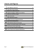
Charts and Figures 1 2 3 4 5 6 7 8 9 10 11 12 13 14 Page 8 Typical SMD Dryer Components 11 Typical Dryer Air Flow Schematic 12 SMD Series Floor-Mount Dimensions 13 Suggested Lift Rigging for SMD Dryers (Floor Mount) 25 Dryer Hose Connections to Hopper 26 Typical Control Panel 30 Typical Temperature Controller 31 Setting List for Process Temperature Controller 36 Typical Dew Point Display Monitor 37 Typical Redundant Safety Controller Display 38 Setting List for Redundant Safety Control
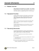
General Information 1-1 1 Models Covered This manual provides instructions for installing and operating Sterling SMD30 and SMD60 membrane dryers. The number designation represents air flow capacity. SMD30 models have a 30 cfm air flow capacity, and SMD60 models have a 60 cfm capacity. 1-2 Equipment Function Sterling membrane mini dryers are designed to generate heated, dehumidified air at carefully controlled temperatures for use in plastic drying systems.
1-4 Standard Features ; Electrical solenoid valve ; Drying temperature range of 160ºF to 400ºF. ; Mitsubishi programmable relay controller ; Display of process temperature set point and actual settings ; Process thermocouple to be connected to drying hopper air inlet.
Figure 1 Typical SMD Dryer Components Standard Air Filter Heater Box High Temperature Switch Membrane Dryer Pressure Switch Pressure Gage Solenoid Valve Compressed Air Inlet Large Particle Filter Coalescing Filter 0.
1-6 The Drying System Sterling Membrane Compressed air dryers, take a small percentage of the dried gas and direct it back in a sweeping pattern through the module shell. This provides a driving force to remove the moisture with the minimum purge required. The Moisture Vent Compressed Air Dryer, consists of thousands of hollow-fiber membranes made of tough temperature and pressure resistant plastic.
Figure 3 SMD Series Floor-Mount Dimensions ON DEW POINT OFF PROCESS TEMPERATURE CONTROL POWER ON OFF ALARM Silencer D ALARM ALARM HORN A B C SMD30 and SMD60 floor-mount dimensions in inches/cm SMD30 SMD60 Dimension in. cm in. A 22 56 25 B 12.75 32 12.75 C 15.5 39 15.5 D 28 71 28 1-7 cm 64 32 39 71 Specifying a Drying System Many variables were considered in the selection of your drying system, including type of materials, residence time, throughput of the extruder or injection molding machine.
Safety 2-1 2 Work Rules Install, operate, and maintain this equipment according to applicable work and safety codes for your location. This includes OSHA, CE, NEC, CSA, SPI, and many other local, national, and international regulations. Obey these specific work rules: Read and follow the instructions in this manual before installing, operating, or maintaining any equipment. Additional copies are available from Sterling. Only qualified persons should work on, or with, this equipment.
2-4 Safety Considerations The terms NOTICE, CAUTION, WARNING, and DANGER have specific meanings in this manual. See Section 13 for a complete list of specific safety warning information. A NOTICE is used to indicate a statement of company policy directly or indirectly related to the safety of personnel or protection of property. A CAUTION indicates a potentially hazardous situation which, if not avoided, may result in minor or moderate injury.
2-5 General Responsibility NO MATTER WHO YOU ARE… Safety is important. Owners, operators, and maintenance personnel must realize that every day, safety is a vital aspect of their jobs. If your main concern is loss of productivity, remember this: Production is always affected in a negative way following an accident.
ONLY YOU can make safety work for you by constantly thinking about what is safe and what is not. It is often the “just once” that an operator reaches into a dryer to remove material and it results in serious injury. Learn and always use safe operation. Cooperate with co-workers to promote safe practices. Immediately report any potentially dangerous situation to your supervisor or appropriate person. REMEMBER: • NEVER place your hands or any part of your body in any dangerous location.
• Clean the dryer and surrounding area DAILY, and inspect the machine for loose, missing or broken parts. • Shut off power to the dryer when it is not in use. Turn the switch to the OFF position, or unplug it from the power source. 2-7 Maintenance Responsibility Safety is essential to the good health of both operator and machine. If you are a maintenance worker, you must make safety a priority in order to effectively repair and maintain equipment.
Do not restore power to the dryer until all persons are clear of the area. DO NOT start and run the dryer until you are sure all parts are functioning correctly. BEFORE you turn the dryer over to the operator for production, verify all dryer enclosure panels, guards and safety devices are in place and functioning properly. 2-8 Safety 2-8-1 Description and Objectives This section includes information on safety devices and procedures that are inherent to the SMD Dryer.
2-8-3 Fail Safe Operation If a safety device or circuit should fail, the design must be such that the failure causes a “Safe” condition. As an example, a safety switch must be a normally open switch. The switch must be held closed with the device it is to protect. If the switch fails, it will go to the open condition, tripping out the safety circuit. At no time should the safety device fail and allow the operation to continue.
-Notes- SMD Series Dehumidifying Dryers Page 21
Shipping Information 3-1 3 Unpacking and Inspection You should inspect your Sterling dehumidifying dryer for possible shipping damage. If the container and packing materials are in reusable condition, save them for reshipment, if necessary. Thoroughly check the equipment for any damage that might have occurred in transit, such as broken or loose wiring and components, loose hardware and mounting screws, etc. In case of breakage, damage, shortage, or incorrect shipment, refer to the following sections.
3-3 If the Shipment is Not Complete Check the packing list. The apparent shortage may be intentional. Back-ordered items are noted on the packing list. You should have: ; SMD Series dryer ; Bill of lading ; Packing list ; Operating and Installation packet ; Electrical schematic and panel layout drawings ; Component instruction manuals Re-inspect the container and packing material to see if you missed any smaller items during unpacking.
Installation 4-1 4 Work Rules The installation, operation, and maintenance of this equipment must be conducted in accordance with all applicable work and safety codes for the installation location. This may include, but is not limited to, OSHA, NEC, CSA, and any other local, national, and international regulations. 4-2 • Read and follow these operating instructions when installing, operating, and maintaining this equipment.
CAUTION! • Use caution and observe safety rules when lifting and placing your dryer! Figure 4 Suggested Lift Rigging for SMD Dryers (Floor Mount) USE Overhead Crane ON DEW POINT OFF PROCESS TEMPERATURE CONTROL POWER ON OFF ALARM ALARM HORN ALARM Silencer USE FORK LIFT TRUCK Note: Floor Mounted Dryers can be lifted by hoist or fork lift. 4-3 Making Electrical Connections ; The serial tag lists voltage, phase, and amp draw information.
SMD30 and SMD60 Electrical Schematics Refer to your Customer Information Packet on actual drawings for your specific dryer. 4-4 Making Dryer/Drying Hopper Process Air Connections Floor Mount Models ; Use high-temperature flexible dryer hose or rigid tubing to connect the dryer to the drying hopper. ; Keep the delivery hose to the drying hopper as short as possible to minimize heat loss. We strongly recommend insulated hose for maximum energy savings. ; Make sure that hoses are not kinked or collapsed.
4-5 Drying Hopper Air Trap Considerations Sterling’s exclusive air trap assembly on the top of the drying hopper prevents ambient air from contaminating the material being dried. ; Keep the material level at the mid point of the air trap for the dryer to operate efficiency. ; Use a hopper loader or vacuum conveying system to maintain the proper material level.
- Notes - Page 28 SMD Series Dehumidifying Dryers
Controls 5-1 5 Identifying Control Panel Indicator Lights and Switches for Standard Controller Switches System OFF/ON/START Switch The OFF/ON/START switch energizes or de-energizes control power to the indicator panel and starts the dryer. (The controller can be energized without the dryer running.) Optional Alarm Silence Switch Press the ALARM SILENCE switch to silence the horn when a high temperature process/ regeneration or blower failure alarm activates.
Figure 6 Typical Control Panel Page 30 SMD Series Dehumidifying Dryers
5-2 Process Air Temperature Controller Sterling dryers use a microprocessor-based PID temperature controller for maintaining process air temperature. The controller is a modular, self-contained unit you can remove from the mounting housing. All parameters except for the process air set point are factory set and adjusted; normally, no field adjustment to the internal controls is necessary.
5-3 Identifying Process Air Temperature Controller LED Indicators —— PV —— Process Value Numeric LED During normal operation, the process value (PV) numeric LED indicator displays the process temperature at the To Process thermocouple. It also lists parameters during setup and error messages if any errors occur. —— SV —— Set Value Numeric LED During normal operation, the set value (SV) numeric LED indicator displays the process set point temperature selected for the dryer.
5-4 Identifying Temperature Controller Keys Mode Key Press the Mode key to shift the display to the next set of parameters. The menu screen displays. Down Key Press the Down arrow key to lower the process air set point temperature. During setup, it lets you decrease the value of the parameter displayed on the set point LED readout. Up Key Press the Up arrow key to raise the process air set point temperature.
5-6 Restoring the E5CN Temperature Controller to Factory Setup If the preset parameters on the controller have been tampered with and it no longer properly controls temperature and displays dew point, you can restore the controllers to the factory setup. Call the Service Department at Sterling for detailed instructions. E5CN Operating Parameters The E5CN controller has several mode selections. Within each mode are numerous parameters that can be set.
Proportional Band Mode(P) This setting controls the amount in which the manipulated variable (MV) is proportionate to the deviated value or controller error. Integral Time Mode (I) Setting this feature, gives the control an action that is proportionate to the time integral of the control error. By using this setting, proportional action is used in combination with integral action to offset the control error and the set point will begin to match the control temperature (PV or process value).
Figure 8 Setting List for Process Temperature Controller (E5CN), Part No. A0555757 Mode Parameter Operation Run/Stop Operation Alarm value 1 Mode Adjustment Adjustment Adjustment Adjustment Adjustment 5-7 Parameter AT execute/cancel Temperature input shift Proportional Band Integral Time Derivative Time Setting range Run/Stop -1999 to 9999 Default Run 0 Sterling setting 25 Setting range ON, OFF -199.9 to 999.9 0.1 to 999.9 0 to 3999 0 to 3999 Default OFF 0.0 8.
Figure 9 Typical Dew Point Display Monitor PV -40 OUT1 SV OUT2 MANU STOP RMT -10 AT SUB1 AT OMRON E5CK (Note: The only functional buttons on this contoller are the up and down keys.) 5-8 Setting the High Dew Point Alarm The high dew point alarm setting is changed by pressing the up and down keys to input the alarm value. The factory setting for Alarm Value 1 (AL-1 ) is -10°F (-23°C).
5-10 Redundant Safety Controller Display Optional The Redundant Safety Controller limits the process air temperature from exceeding the upper temperature range set by the E5CN Temperature Controller. Standard Sterling dryers use a microprocessor-based controller for limiting the process air temperature. The controller is a modular, self-contained unit removable from the mounting housing. All parameters are factory set and adjusted; normally, no field adjustment to the internal controls are necessary.
WATLOW Operating Parameters The WATLOW controller has only one mode selection; ALARM. The factory at Sterling sets the security level to protect the critical parameters from being accidentally changed. Below is an explanation of the modes you will have access to and the Sterling default settings. Entering Operating Parameters to Select Modes To enter the display: 1. Press both the Up and Down keys for three seconds from the home page.
Figure 11 Setting List for Redundant Safety Controller (WATLOW), Part No. A0555757 Mode SEn Lin C-F S.dEC IS.En Sc.Lo Parameter Sensor Type Thermocouple Linearization Temperature Units Temp. Decimal Places INFOSENSE™ Process Scale Low Sc.hi Process Scale High CAL Ftr.
Control Operation 6-1 6 Controller Operation (Without Optional Alarm Horn & Reset Button) 1.) Turn the disconnect on the control panel to the ON position. Power is applied to the voltage line fuses, line side of the control power switch and the temperature controller. 2.) Turn the control power switch to the ON position. Power is applied to the programmable relay and dew point controller. Note: The relay screen which contains the Alarm Display Messages is located inside the controller enclosure.
6.) When no fault conditions exist, the display reads “SYSTEM NORMAL”. 7.) When a dew point fault is generated by the optional dew point controller, the alarm horn and light will activate. The alarm light will flash, indicating a non-critical fault. Press Alarm Reset to deactivate the alarm until the next dew point fault occurs. 8.) The dryer is shut off by turning the control power switch to the OFF position. 9.) Refer to Schematic drawing A0566087 enclosed in the control enclosure.
4.) If the OMRON controller faults, the optional redundant high temperature safety device opens, or the process heater safety switch opens, a process heater fault is generated. “HIGH TEMP” is displayed on the relay screen. The alarm light is activated. The process heater, regen heater, and process/regen blower are turned off. Pressing the ALARM RESET pushbutton will deactivate the alarm horn and light. Turn the Off-On-Start switch to the START position to restart the dryer.
6-3 Alarm Display Messages Note: The relay screen which contains the Alarm Display Messages is located inside the controller enclosure.
Startup, Shutdown, and Operation 7-1 7 Pre-Startup Checks ; Check the process hose for tight connections. ; Check hopper exhaust filter for tight connection. ; Check all companion equipment, such as the drying hopper; verify that the loading system is ready for operation. ; Verify that all dryer electrical connections are tight. Important! Clean the rust-preventing oil from inside the drying hopper. Failure to clean the hopper fouls the desiccant and voids your warranty! 7-2 Starting Up the Dryer 1.
7-3 Shutting Down the Dryer 1. When processing is complete, close the hopper slide gate and shut down any in-line companion equipment. 2. Turn the Dryer ON/OFF selector switch to OFF. 3. Turn the system ON/OFF switch to OFF. If needed, empty the drying hopper. 4. For maintenance or a long term shutdown, open (de-energize) the electrical disconnects at the dryer and at the power drop.
Maintenance 8-1 8 Work Rules The installation, operation, and maintenance of this equipment is to be conducted in accordance with all applicable work and safety codes for the installation location. This may include, but is not limited to, OSHA, NEC, CSA, and any other local, national, and international regulations. In addition, you must observe the following specific work rules: ; Keep these operating instructions on hand and follow them when installing, operating, or maintaining your dryer.
Recommendations for Cleaning and Replacing Filters 1. Turn off and/or lock out electrical power to the dryer. 2. Remove the back access cover. 3. Locate the 2 compressed air hoses and filter bowls connected to the filters. 4.
5. Locate filters. 6. Remove the filters. 7. Replace particulate filter with new element. 8. Replace coalescing filter with new element.
After each cleaning: 8-3 • Inspect the filter element. Briefly hold a light bulb behind the element and look for any fatigued paper or residual dirt. Inspect for holes and tears by looking though the filter toward a bright light. Check for damaged gaskets or dented metal parts. Do not re-use a damaged filter! • Check the gasket for damage. A damaged gasket allows contaminants into the process. Replace as needed.
Figure 12 Process Heater Location and Disassembly Undo (6) 10-32 Button Head Screws using 1/8 Allen Wrench 1" Wide x 1/8" Thick High Temperature Gasket (2) 4-40 screws Hi Temperature Snap Switch Procedures 1. Remove the four (4) 10-32 button head screws securing the process heater access cover using a 1/8” Allen wrench. 2. Sketch the heater wiring configuration so you can properly rewire the heater. 3. Remove the wires to the heater plate assembly being removed or replaced. 4.
Preventive Maintenance Checklist Sterling SMD Dehumidifying Dryers System model # Every week Serial # Date/ By Date/ By Date/ By Date/ By Date/ By Date/ By Date/ By Date/ By Date/ By Date/ By Date/ By Date/ By Date/ By Inspect all filters for wear, replace/ clean if dirty or worn. Check to make sure that all hose conections are air tight. Every month Jan Feb Mar Apr May Jun Jul Aug Sep Oct Nov Dec Lock out electrical power and inspect electrical wiring for integrity.
Troubleshooting Problem 9 Possible cause Process heaters are faulty. Loss or reduction of process air temperature. Solid-state temperature controller faulty. Process temperature was adjusted in error by plant personnel. Process heaters are faulty. Loss or reduction in drying capacity. PLC Regeneration Bed LED indicators both off. PLC Regeneration Heater Left/Right output indicators both off. Material being dried differs from material specified at the time of purchase.
Problem Possible cause Process temperature set too high due to operator error. Material in drying hopper cakes, or meltdown occurs. Poor dew point performance. Nothing displays when the controller is turned on. High temperature alarm not set properly. Process set point is out of acceptable range. Function set for degrees Celsius (ºC), set point at degrees Fahrenheit (ºF). Page 54 Reset high temperature alarm. Restore temperature controller to factory pre-sets.
Problem Possible cause Input polarity on thermo-couple is wrong or connection is wrong. Properly wire the terminals. Input-type setting is incorrect. Properly set the input with the input-type selector rotary switch. No compensating lead wires used for extension of the thermocouple. Use proper compensating lead wires and terminals. Thermocouple and controller are connected by wires other than proper lead wires. Process value is abnormal or not obtained.
Dryer Options 10 The following is a list of options, which your Dryer may have been equipped with: • • • • • Page 56 Dew Point Monitor Audible Alarm with Silence Button High Temperature Option (with Aftercooler) Casters AP1 PLC Control System SMD Series Dehumidifying Dryers
11 Spare Parts 11-1 Spare Parts List SMD Series Dehumidifying Dryers LEVEL 1 ( Mechanical Components ) PART # SIZE Description W00015435 Dew Point Sensor Insert Cable A0548556 Dew Point Sensor A0568459 Coalescing Filter Element A0568458 Particulate Air Filter Element A0566859 Membrane Air Dryer W00013983 High Temperature Gasket. A0566676 High Temperature Snap Switch. A0568009 Pressure Switch A0556547 Solinoid Valve A0566682 Dew Point Sample Hose 1/4'' O.D.
LEVEL 2 ( Electrical Components ) PART # SIZE Description A0530042 Mercury Heater Contactor A0567917 Process Air Temperature Controller A0544089 Regeneration Air Temperature Controller A0558065 * Dew Point Monitor A0548555 * Dew Point Circuit Board A0505417 Regeneration T'Couple Relay LEVEL 2 ( Mechanical Components ) PART # SIZE Description A0548621 Ceramic Cap for the End of Heater Elements A0566483 1250 Watts Heater Element 208/220 Volts A0566484 1250 Watts Heater Element 230 Volts A0566485 1250 Watts He
Technical Assistance 12 12-1 Contact Information for Technical Assistance Parts Department Call toll-free 7am–5pm CST [800] 423-3183 or call [414] 354-0970, Fax [414] 354-6421 The ACS Customer Service Group will provide your company with genuine OEM quality parts manufactured to Sterling engineering design specifications, which will maximize your equipment’s performance and efficiency.
12-2 Returned Material Policy 12-2-1 Credit Returns 1. Prior to the return of any material authorization must be given by Sterling. A RMA number will be assigned for the equipment to be returned. 2. Reason for requesting the return must be given. 3. ALL returned material purchased from Sterling returned is subject to 15% ($75.00 minimum) restocking charge. 4. ALL returns are to be shipped prepaid. 5. The invoice number and date or purchase order number and date must be supplied. 6.
12-3 Warranty Sterling warrants all equipment manufactured by it to be free from defects in workmanship and material when used under recommended conditions. The Company’s obligation is limited to repair or replace FOB the factory any parts that are returned prepaid within one year of equipment shipment to the original purchaser, and which, in the Company’s opinion, are defective. Any replacement part assumes the unused portion of this warranty.
-Notes- Page 62 SMD Series Dehumidifying Dryers
Safety Tag Information 13 13-1 SMD Dryer Safety Tags Hot! Read Operation and Installation Manual High Voltage Inside Enclosure Earth Ground PE Lifting Point SMD Series Dehumidifying Dryers Protected Earth Ground Page 63
13-2 Dryer Identification (Serial Number) Tag (Located on back of Dryer) SMD Series Dryer Model Number SMD-030 Max Drying Capacity HR 460V Serial Number 060701R 1Ǿ Date of Manufacture 06/2003 4.5A Over-current Protection Device (s) 4.5A Total Frequency 50/60Hz Compressed air supply None Dryer Mass 400 lbs/(180 KG) Electrical Diagrams & Pneumatic Diagram 5200 W. Clinton Ave.
Service Notes SMD Series Dehumidifying Dryers Page 65
Service Notes Page 66 SMD Series Dehumidifying Dryers
Sterling warrants all equipment manufactured by it to be free from defects in workmanship and material when used under recommended conditions. The Company’s obligation is limited to repair or replace FOB the factory any parts that are returned prepaid within one (1) year of equipment shipment to the original purchaser, and which, in the Company’s opinion, are defective. Any replacement part assumes the unused portion of this warranty.
Service Department Call Toll Free (800) 783-7835 Auxiliary Equipment for the Process Industries PO Box 245018 5200 West Clinton Avenue • Milwaukee, WI 53224-9518 (414) 354-0970 • Fax (414) 354-6421 Scrap Recovery Systems Process Heating/ Cooling Automated Parts Removal Material Processing