
user manual


Page 42 SMD Series Dehumidifying Dryers
6.) When no fault conditions exist, the display reads “SYSTEM
NORMAL”.
7.) When a dew point fault is generated by the optional dew point
controller, the alarm horn and light will activate. The alarm
light will flash, indicating a non-critical fault. Press Alarm
Reset to deactivate the alarm until the next dew point fault
occurs.
8.) The dryer is shut off by turning the control power switch to the
OFF position.
9.) Refer to Schematic drawing A0566087 enclosed in the control
enclosure.
6-2 Controller Operation
(With Optional Alarm Horn & Reset Button)
1.) Turn the disconnect on the control panel to the ON position.
Power is applied to the voltage line fuses, line side of the
control power switch and the temperature controller.
2.) Turn the control power switch to the ON position. Power is
applied to the programmable relay and dew point controller.
The solenoid will move to the start position as follows:
2-1. The solenoid opens and air begins to flow. The heaters
are also activated.
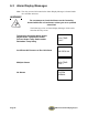
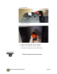
Note: The relay screen which contains the Alarm Display Messages is
located inside the controller enclosure. For a list of Alarm Display
Messages, see Section 6-3 on Page 44.
WARNING!
Do not attempt to check the Alarms on the Controller
located within the unit enclosure unless you are a qualified
electrician!
3.) Once the control power is on and no fault conditions exist,
turning the Off-On-Start switch to the START position will
start the dryer as follows:
3-1. The process heater is turned on and controlled by the
E5CN controller.