GP Series Portable Chillers Part Number: 882.93092.00 Bulletin Number: SC2-620 Effective: 5/1/2009 Write Down Your Serial Numbers Here For Future Reference: _________________________ _________________________ _________________________ _________________________ _________________________ _________________________ We are committed to a continuing program of product improvement. Specifications, appearance, and dimensions described in this manual are subject to change without notice. ECN No.
Shipping Information Unpacking and Inspection You should inspect your equipment for possible shipping damage. Thoroughly check the equipment for any damage that might have occurred in transit, such as broken or loose wiring and components, loose hardware and mounting screws, etc. In the Event of Shipping Damage According to the contract terms and conditions of the Carrier, the responsibility of the Shipper ends at the time and place of shipment.
Table of Contents CHAPTER 1: SAFETY................................................................ 5 1-1 1-2 1-3 How to Use This Manual ............................................................................................. 5 Safety Symbols Used in this Manual .....................................................................5 Warnings and Precautions .......................................................................................... 6 Responsibility .......................................
-1 4-2 4-3 4-4 4-5 4-6 4-7 Panel Buttons, Indicator Lights, and Switches .......................................................... 22 Microprocessor Controller ...................................................................................22 Initial Start-up ............................................................................................................ 23 Status Screens ..........................................................................................................
Chapter 1: 1-1 Safety How to Use This Manual Use this manual as a guide and reference for installing, operating, and maintaining your equipment. The purpose is to assist you in applying efficient, proven techniques that enhance equipment productivity. This manual covers only light corrective maintenance. No other maintenance should be undertaken without first contacting a service engineer. The Functional Description section outlines models covered, standard features, and optional features.
1-2 Warnings and Precautions Our equipment is designed to provide safe and reliable operation when installed and operated within design specifications, following national and local safety codes. To avoid possible personal injury or equipment damage when installing, operating, or maintaining this equipment, use good judgment and follow these safe practices: 9 Follow all SAFETY CODES. 9 Wear SAFETY GLASSES and WORK GLOVES. 9 Disconnect and/or lock out power before servicing or maintaining the equipment.
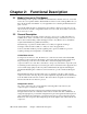
Chapter 2: 2-1 Functional Description Models Covered in This Manual This manual provides operation, installation, and maintenance instructions for air-, water-and remote air-cooled portable chillers. Model numbers are listed on the serial tag. Make sure you know the model and serial number of your equipment before contacting the manufacturer for parts or service.
The refrigerant is compressed in the compressor and flows through the discharge line as a gas to the condenser. There it gives up its heat as it condenses to a liquid in the condenser. An electronic hot gas bypass valve is used to control cooling capacity during intermittent or partial load conditions. This feature contributes substantially to chiller longevity by eliminating excessive cycling of the compressor and providing close temperature control. 2-3 Standard Features Mechanical Features Compressor.
Refrigeration Features • HFC-410a refrigerant • Electronic hot gas bypass capacity control • High refrigerant pressure cutout switches • Suction and discharge pressure transducers.
High Pressure Cutout This electro-mechanical cutout device opens the compressor control circuit if the refrigeration system compressor discharge pressure exceeds 575 psi.. Note: The high-pressure cutout is a manual reset device typically mounted on the compressor discharge line inside the mechanical cabinet. Call a refrigeration service technician to analyze the problem and reset the control.
interlock. The alarm signals anytime that a fault is recognized during the operation of the chiller. Communications Options. RS-485 serial Modbus communications. High Pressure Fans. Provides for an additional 1.0”WC (250 Pa) of static pressure on fan discharge. High-pressure fans are necessary and must be included in chiller installations where exiting air exhausts through ductwork.
Figure 1: Optional Pump Amperages Voltage Construction HP 460/3/60 SS 1 1.7 1.5 2.3 2 4.0 3 4.2 5 8.2 10 12.
Chapter 3: 3-1 Installation Uncrating All models are are shipped mounted on a skid, enclosed in a plastic wrapper, and open-crated on all four sides and top. 1. Pry the crating away from the skid. 2. Use a pry bar to remove the blocks securing the unit to the skid. 3. Lift unit from sides, inserting forklift under the base. The forks must be equidistant from the centerline of the unit and the unit must be balanced on the forks. Lift slowly and only high enough to clear the skid.
3-3 Process Water Connections All of our portable chillers have two chilled water connections. The chilled water supply, labeled “To Process” is the outlet for the chilled water leading to the process being cooled. The chilled water return, labeled “From Process” is the inlet leading from the process back into the chiller to be cooled and re-circulated. All external chilled water connections should be run full size to the process. Flow and pressure information is available in the Appendix.
3-7 Condenser Considerations Water-Cooled Chiller Condensers Water-cooled portable chillers can use city water or tower water as a cooling medium. Make sure that all external piping and connections supplying and discharging water to and from the condenser are full size. You’ll make two connections to the water-cooled condenser: Condenser Water In. The condenser water supply, labeled “Condenser Water In”, is located at the rear of the chiller. It is the inlet for city or tower water.
3-8 Checking Motor Direction All of our portable chillers have their motor rotations properly phased at the factory. If compressors, pumps, or fans are running in reverse rotation, disconnect and lock out the power source and reverse any two power leads into the chiller disconnect switch. Caution! Do not switch leads at the motors, motor starters, or contactors. Three-Phase Compressors Scroll compressors are directionally-dependent and compress in one rotational direction.
3-9 Water Reservoir All portable chillers shipped during the fall, winter, or spring, or those units that are shipped from stock are flushed at the factory with a water/ethylene glycol solution to prevent piping components prone to retaining water from freezing.
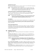
Figure 2: Ethylene Glycol and Propylene Glycol Curves Pe rce n t G lyc o l Cu rves fo r F ree ze P ro tec tion 40.0 30.0 Eth ylene G lycol 20.0 P rop ylene G lyc ol 10.0 0.0 -10.0 -20.0 -30.0 -40.0 -50.0 -60.0 0.0 10.0 20.0 30.0 40.0 50.0 60.0 % Gl ycol by Vol um e Example: 45°F set point minus 20°F = 25°F. From Figure 28, 25°F equates to 10% by volume of glycol required.
3-10 Automatic Water Make-Up Option The chiller may be connected to an automatic make-up system if the optional package (pipe fittings, solenoid valve and 1/2” NPT city water make-up connection) is factory installed. If the automatic make-up system is connected to a city water system, make provisions to prevent backflow contamination. Install an approved backflow preventer in accordance with local codes.
Operator Password. If you define a password for operators, then a password will be required to carry out any fuction (other than reviewing the status screens). Entering the operator’s password will give the user access to the setpoints for leaving temperature, high temperature warning, high temperature fault. Supervisor Password. If you define a password for supervisors (or setup personnel) then most settings can be changed only after entering the password.
6. Press to accept the Password and move to the next line. 7. For either Operator or Supervisor password the time that the password will allow the controller to be active can be set by the Operator or Supervisor Password Time. With the or to increment or decrement the time. The PW Time value highlighted, press password time for either setup can be from 0 to 99 minutes.
Chapter 4: 4-1 Operation Panel Buttons, Indicator Lights, and Switches Microprocessor Controller The standard chillers use a microprocessor-based PID controller. The Carel PCO controller along with the Carel PGD1 Interface is a modular, self-contained unit that can slide from its mounting housing. It is factory set and adjusted; no field adjustment to the internal controls is necessary. The standard operation range is 20ºF to 80ºF (-7ºC to 27ºC).
4-2 Initial Start-up 1. Verify the initial start-up checklist from Chapter 3, Section 3-11. 2. With the main supply power switch in the ON position, the screen will display the version of the software for a period of 5 seconds, and then display the main status screen. Figure 4 - Main Status Screen 3. Set the Leaving Fluid temperature by depressing the the menu. button to display Figure 5 - Menu Screen or button to highlight SETPOINTS and press . If 4.
Enter the established Operator Password by depressing the to move the position of the cursor, and then depressing the or button to increment or decrement the number. Once all of the numbers have been entered depress the appear. to accept the password. The following screen will Figure 6 - Operator Setpoints Screen to move the cursor to the Leaving Temp line. Use the 5. Depress button to increment or decrement the value. Depress value and move the cursor down one line. 6.
Elevated sound level and substantially reduced current draw indicate reverse rotation. After several minutes of operation, the compressor internal protector trips. 4-3 Status Screens The controller has eight (8) preconfigured status screens. The main status screen (shown in Figure 11) shows the main operating points of the chiller: Entering and Leaving fluid temperatures; Leaving fluid sepoint, pump discharge pressure, tank fluid level (depth) , and percentage of hot-gas bypass output.
4-4 Access Levels The controller is setup to allow access to three distinct password groups: operator, supervisor, and service.
Warning, and Hi Temp Fault setpoints. Supervisor access allows the supervisor to modify the above plus Selecting any of the menus in the Menu Screen will display the Password Screen.
4-5 Controller Setpoints Variable Leaving Temp Description Temperature of fluid out to process Low Temperature Warning Setpoint for alarm to warn when leaving fluid temperature is too high Setpoint to shut down pump and compressor based on leaving fluid temperature Temperature Difference between Leaving Fluid Temperature and Setpoint to turn on the compressor Temperature Difference between Leaving Fluid Temperature and Setpoint to turn off the compressor Delay time in seconds between fault and stopping
1. Set the Leaving Fluid temperature by depressing the the menu. button to display Figure 8 - Menu Screen 2. Depress the or button to highlight SETPOINTS and press . If passwords were setup (See Section 3-12 for information on the controller passwords) the password screen will appear. Enter the Operator Password by depressing the to move the position of the cursor, and then depressing the or button to increment or decrement the number.
the to accept the password. The following screen will appear. Figure 9 - Operator Setpoints Screen 3. Depress to move the cursor to the Leaving Temp line. Use the button to increment or decrement the value. Depress value and move the cursor down one line. or to accept the 4. Adjust the Hi Temp Warning and Hi Temp Fault in the same manner. 5. Depress the 4-6 button twice to return to the main status screen.
GP Series Portable Chillers Chapter 4: Operation 31 of 44
Chapter 5: 5-1 Maintenance Lubrication Grease all blower bearings, fan and blower motors, and pump motors that do not have permanently sealed bearings. Be sure to use an all-purpose industrial grease with a temperature reference of 185˚ F (85˚ C). Remove the grease relief plug (motors only) before adding grease, add grease until a small amount pours out, and replace the plug when finished.
Caution! Do not use steam or water over 140ºF (60ºC) to clean a condenser unless you are monitoring the refrigeration circuit for excessive pressure with gauges. Only a trained technician should use this method. 5-4 Maintaining the Evaporator Dirty evaporator heat exchange surfaces reduce system capacity and efficiency. Remove dirt and slime in the evaporator by reverse-circulating with a mild detergent and water solution.
Chapter 6: Problem Troubleshooting Possible cause No power. Wrong voltage supplied to unit. Defective on/off switch. Unit does not run. Control circuit fuse blown. Defective control transformer. Piping flow switch circuit open. Pump motor off on overload. Leaving fluid setpoint set higher than temperature of liquid in system. Defective leaving fluid sensor High/Low thermostat. Compressor internal overload or fuses are open. Pump runs; compressor does not. Compressor contactor holding coil open.
Problem Pump pressure low (refer to curves for normal pressure for various pumps). Possible cause Pump running in reverse. Check for foreign matter. Pump pressure is too high. Restricted water flow. Restricted condenser air flow. Unit runs continuously, but not enough cooling power. GP Series Portable Chillers Unit low on refrigerant. Compressor not operating efficiently. Unit under-sized for application.
Chapter 7: 7-1 Appendix Returned Material Policy Credit Returns Prior to the return of any material, authorization must be given by the manufacturer. A RMS number will be assigned for the equipment to be returned. Reason for requesting the return must be given. All returned Material purchased from the manufacturer is subject to 15% ($75.00 minimum) restocking charge. All returns are to be shipped prepaid. The invoice number and date or purchase order number and date must be supplied.
7-2 Technical Assistance Parts Department Call toll-free 7am–5pm CST [800] 423-3183 or call [262] 641-8610, Fax [262] 641-8653 The ACS Customer Service Group will provide your company with genuine OEM quality parts manufactured to engineering design specifications, which will maximize your equipment’s performance and efficiency. To assist in expediting your phone or fax order, please have the model and serial number of your unit when you contact us.
7-3 Specifications Air-Cooled Portable Chillers Nominal operating parameters for air-cooled models are 50ºF (10ºC) leaving water temperature at 2.4 gpm per ton (9.1 lpm per 3.517 kW) with 95ºF (35ºC) ambient air. For 50 Hz applications, multiply capacity by 0.83. Nominal 60 Hz capacity flow rate must be maintained. G-PAC-20 PERFORMANCE (NOMINAL DESIGN CONDITIONS) COOLING CAPACITY 4.
G-PAC-40 PERFORMANCE (NOMINAL DESIGN CONDITIONS) COOLING CAPACITY 10.11 TONS ALTITUDE SEA LEVEL COOLANT SUPPLY TEMPERATURE 50 °F COMPRESSOR POWER 9944 WATTS AMBIENT AIR TEMPERATURE 95 °F EER 12.
Water-Cooled Portable Chillers Nominal operating parameters for water-cooled models are 50ºF (10ºC) leaving water temperature at 2.4 gpm per ton (9.1 lpm per 3.517 kW) with 85ºF (29ºC) tower water. For 50 Hz applications, multiply capacity by 0.83. Nominal 60 Hz capacity flow rate must be maintained. G-PWC-20 PERFORMANCE (NOMINAL DESIGN CONDITIONS, 60 HZ) COOLING CAPACITY COOLANT SUPPLY TEMPERATURE CONDENSER INLET WATER TEMPERATURE COOLANT COOLANT FLOW UNIT PRESSURE DROP 5.
COOLANT SUPPLY TEMPERATURE CONDENSER INLET WATER TEMPERATURE COOLANT COOLANT FLOW UNIT PRESSURE DROP 50 °F 85 °F WATER 27 GPM 7 PSID COMPRESSOR POWER 8323 WATTS EER 16.31 BTU/WATT CONDENSER WATER FLOW SOUND POWER LEVEL SOUND PRESSURE LEVEL @ 1 METER 33.93 GPM dBA dBA OPERATING PARAMETERS COOLANT SUPPLY TEMPERATURE CONDENSER INLET WATER TEMPERATURE 20-80 °F COOLANT FLOW 50-90 °F MINIMUM LOAD 30 GPM 2.
7-4 Pump Curves, Flow, and Pressure Considerations 60 Hertz Pump Curves 300 120 250 100 design 4 design 3 3U 32-200-1-10HP 200 5 HP 2CDX 200/506 3U 32-200-1-7.5HP Psi Head [ft] 2CDX 120/406 80 150 1.
Calculating Chiller Nominal Flow and Pressure to Process • Flow rate: Obtain the flow reading from the appropriate pump curve. • Pressure: Obtain a corresponding pressure reading from the pump curve you selected, then subtract the one-pump pressure drop listed in the above table using the appropriate chiller hp and flow rate. • For two-pump (Process/Recirc) chillers, do not subtract pressure drop from table above for process pump.
7-5 Electrical Schematic Please refer to your owner’s information packet for more details regarding your specific unit.