INSTALLATION INSTRUCTIONS AND PARTS IDENTIFICATION NXIM-5 J30-09590 HIGH EFFICIENCY GAS-FIRED PROPELLER UNIT HEATERS ATTENTION: READ THIS MANUAL AND ALL LABELS ATTACHED TO THE UNIT CAREFULLY BEFORE ATTEMPTING TO INSTALL, OPERATE OR SERVICE THESE UNITS! CHECK UNIT DATA PLATE FOR TYPE OF GAS AND ELECTRICAL SPECIFICATIONS AND MAKE CERTAIN THAT THESE AGREE WITH THOSE AT THE POINT OF INSTALLATION. RECORD THE UNIT MODEL AND SERIAL No. (s) IN THE SPACE PROVIDED. RETAIN FOR FUTURE REFERENCE. Unit No. Serial No.
TABLE OF CONTENTS DESCRIPTION.............................................................. 2 GENERAL SAFETY INFORMATION............................. 3 Installation Codes........................................................ 3 Special Precautions..................................................... 3 SPECIFICATIONS......................................................... 4 Performance & Dimensional Data............................4-5 INSTALLATION............................................................
GENERAL SAFETY INFORMATION Failure to comply with the general safety information may result in extensive property damage, severe personal injury, or death. This product must be install be a licensed plumber or gas fitter when installed within the Commonwealth of Massachusetts. Installation must be made in accordance with local codes, or in absence of local codes, with the latest edition of the ANSI Standard Z223.1 (N.F.P.A. No. 54) National Fuel Gas Code.
SPECIFICATIONS Figure 2 - Dimensional Drawing – High Efficiency Unit Heater Size 50 Dimensional Data COMBUSTION AIR "N" "L" "D" "F1" (HANGING) FLUE "K" "W" "P" GAS CONNECTION "J" "T" "U" ELECTRICAL CONNECTION "E" (HANGING) "R" "Q" "S" REAR VIEW "G" (DISCHARGE OPENING) ELECTRICAL CONTROL BOX "F2" (HANGING) 3" (77mm) "A" 4 SUSPENSION POINTS (THREADED RODS) "M" "H" (DISCHARGE OPENING) "C" BOTTOM VIEW TOP VIEW "B" FRONT VIEW UNIT HEATER 50 SIZE Size 100-400 Dimensional Data ELECTRICAL
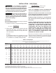
Table 1 - Performance and Dimensional Data - High Efficiency Unit Heater Unit Capacity (MBH) PERFORMANCE DATA† Input Output Thermal Efficiency Free Air Delivery Air Temperature Rise Condensate Production Full Load Amps at 120V Minimum Circuit Amps at 120V Max. Overcurrent Protection at 120V MOTOR DATA: DIMENSIONAL DATA - inches (mm) "A" Height to Top of Combustion Air Inlet BTU/Hr. (kW) BTU/Hr. (kW) (%) CFM (cu. m/s) Deg. F (Deg C.
INSTALLATION Do not install unit heaters in corrosive or flammable atmospheres! Premature failure of, or severe damage to the unit will result! Avoid locations where extreme drafts can affect burner operation. Unit heaters must not be installed in locations where air for combustion would contain chlorinated, halogenated or acidic vapors.
INSTALLATION (continued) Make certain that the lifting methods used to lift the heater and the methods of suspension used in the field installation of the heater are capable of uniformly supporting the weight of the heater at all times. Failure to heed this warning may result in property damage or personal injury! Make sure that the structure to which the unit heater is to be mounted is capable of safely supporting its weight.
Figure 3C - Heater Mounting: Steel Construction (for all sizes) Figure 3D - Heater Mounting: Wood Construction Joists (for sizes 50/200) :22' &216758&7,21 -2,676 WASHER & NUT JOIST 2" X 6" LAG BOLTED ACROSS JOISTS LAG BOLT & WASHER 3/8'' THREADED ROD THREADED INSERT UNIT HEATER 50/200 SIZES Figure 3E - Heater Mounting: Wood Construction Joists (for sizes 300/400) :22' &216758&7,21 -2,676 NUT & WASHER JOIST 2" X 6" LAG BOLTED ACROSS JOISTS Table 2 - Max. & Min.
INSTALLATION – GAS PIPING To avoid damage or possible personal injury, do not connect gas piping to this unit until a supply line pressure/leak test has been completed. Connecting the unit before completing the pressure/leak test may damage the unit gas valve and result in a fire hazard. 200,000 BTU/Hr = 200 Cu. ft./hr. 1,000 BTU/cu. ft. Using Table 3, a 1 inch pipe is needed. Do not rely on a shut-off valve to isolate the unit while conducting gas pressure/ leak tests.
INSTALLATION – GAS PIPING (continued) PIPE INSTALLATION 1. Install the gas piping in accordance with applicable local codes. 2. A field provided lock-up type high pressure regulator must be used to limit the supply pressure to a maximum of 14 inches W.C. (3.5 kPa). All piping should be sized in accordance with the latest edition of ANSI Standard Z223.1 (NFPA 54), National Fuel Gas Code; in Canada, according to CSA B149. See Table 3 for correct gas piping size.
INSTALLATION – CONDENSATE PIPING The condensate trap provided with the unit must be installed. The condensate trap is designed to provide backpressure for the correct operation of the unit. Do not use a traditional plumbing “P” trap. NOTICE: The design of the condensate trap assembly provided with the unit has changed. Figure 5A and Table 4 apply to the original trap design; Figure 5B applies to the current trap design. The installation steps below apply to both trap designs.
ELECTRICAL CONNECTIONS HAZARDOUS VOLTAGE! DISCONNECT ALL ELECTRIC POWER INCLUDING REMOTE DISCONNECTS BEFORE SERVICING. Failure to disconnect power before servicing can cause severe personal injury or death. Standard units are shipped for use on 115 volt, 60 hertz, single phase electric power. The motor name-plate and electrical rating of the transformer should be checked before energizing the unit heater electrical system. All external wiring must conform to the latest edition of ANSI/NFPA No.
ELECTRICAL CONNECTIONS (continued) Figure 7A – Unit Wiring Diagram, High Efficiency Unit Heater Size 50, Equipped with Natural or Propane (LP) Gas, Modulating with Outside Air Reset (Master) 13
ELECTRICAL CONNECTIONS (continued) Figure 7B – Unit Wiring Diagram, High Efficiency Unit Heater Size 100, Equipped with Natural or Propane (LP) Gas, Modulating with Outside Air Reset (Master) 14
ELECTRICAL CONNECTIONS (continued) Figure 7C – Unit Wiring Diagram, High Efficiency Unit Heater Size 150/200, Equipped with Natural or Propane (LP) Gas, Modulating with Outside Air Reset (Master) 15
ELECTRICAL CONNECTIONS (continued) Figure 7D – Unit Wiring Diagram, High Efficiency Unit Heater Size 300/400, Equipped with Natural or Propane (LP) Gas, Modulating with Outside Air Reset (Master) Figure 7E – Alternate Wiring Diagram Section J8 for Size 150-400 Units Manufactured with Fenwal Ignition Control Board 16
VENTING – GENERAL GUIDELINES ANSI now organizes vented appliances into four categories. Venting Categories Non- Condensing Condensing Negative Vent Pressure Positive Vent Pressure I II III IV Category I Includes non-condensing appliances with negative vent pressure, like the traditional atmospheric unit heater. Category II Groups condensing appliances with negative vent pressure. Category IV Covers condensing appliances with positive vent pressure.
VENTING – GENERAL GUIDELINES The filter box must be installed prior to unit operation. Failure to do so may result in damage to the burner assembly. NOTICE: The filter is only designed to prevent large debris from entering the burner assembly. If there are other contaminants in the space air, the unit should be installed as separated combustion to take outside air into the unit for combustion.
STANDARD COMBUSTION – HORIZONTALLY VENTED UNIT HEATERS (CATEGORY IV) This appliance uses a positive pressure venting system. All joints must be sealed completely to prevent leakage of flue products into occupied spaces. Failure to do this may result in severe personal injury, death or major property damage. 1. Horizontal venting arrangements are designed to be used with schedule 40 vent pipe. All heaters should be vented with UL 1738 listed vent pipe.
STANDARD COMBUSTION – VERTICALLY VENTED UNIT HEATERS (CATEGORY IV) This appliance uses a positive pressure venting system. All joints must be sealed completely to prevent leakage of flue products into occupied spaces. Failure to do this may result in severe personal injury, death or major property damage. 1. Vertical venting arrangements are designed to be used with schedule 40 vent pipe. All heaters should be vented with UL 1738 listed vent pipe.
SEPARATED COMBUSTION – TWO PIPE VENTING NOTE: For non-concentric venting (two wall or two roof penetrations, one for combustion air and a second for flue pipe), follow the instructions below. For concentric venting (single wall or roof penetration), follow the concentric venting instructions in SEPARATED COMBUSTION – CONCENTRIC VENTING Section. AIR INLET COLLAR When unit is to be used in a separated vent system, the inlet collar will be connected to the combustion air intake pipe.
Figure 11 - Vertical Two Pipe Separated Combustion Venting, Roof Termination 24" (610 mm) MINIMUM FROM ADJACENT WALL OR BUILDING TO COMBUSTION AIR INLET TERMINAL 4.5" MINIMUM (115 mm) 4.
SEPARATED COMBUSTION – CONCENTRIC VENTING NOTICE: Every Separated Combustion unit to be installed MUST use the factory-available Concentric Vent Kit. If you do not have this kit, contact the manufacturer ASAP to obtain one prior to installation. AIR INLET COLLAR When the unit is to be used in a separated vent system, the inlet collar will be connected to the combustion air intake pipe. The inlet collar is located on the bottom panel of size 50 units, and on the top panel of size 100-400 units.
SEPARATED COMBUSTION – CONCENTRIC VENTING (continued) 4. Cut a hole for Concentric Vent kit. a. Cut a 4 inch (102 mm) diameter hole for size 50/150 unit, 2 inch (51 mm) concentric vent kit. b. Cut a 5 inch (127 mm) diameter hole for size 200 unit, 3 inch (76 mm) concentric vent kit. c. Cut a 6 inch (152 mm) diameter hole for size 300/400 unit, 4 inch (102 mm) concentric vent kit. Figure 16 - Horizontal Sidewall Concentric Venting, Single Termination ROOF OVERHANG 5. Partially assemble Concentric Vent kit.
SEPARATED COMBUSTION – CONCENTRIC VENTING (continued) NOTE: Keep assembly free of insulation during installation. Figure 19 - Vertical Concentric Vent Kit Installation NOTE: Maintain clearance dimensions as shown in Figures 16, 17 and 18. Also refer to Table 5 for vent termination clearance requirements. NOTE: If assembly is too short, the two pipes supplied in the kit may be replaced by using same diameter, field supplied SDR-26 PVC (ASTM D2241) pipe.
GAS CONVERSION This conversion kit shall be installed by a qualified service agency in accordance with the manufacturer's instructions and all applicable codes and requirements of the authority having jurisdiction. If the information in these instructions is not followed exactly, a fire, explosion or production of carbon monoxide may result causing property damage, personal injury or loss of life.
GAS CONVERSION Figure 22A – Gas Valve Adjustment Locations (Sizes 50/200) Unit Size (MBH) Natural Gas to Propane (LP) Gas 1/2 CW 1-3/4 CW 1-1/2 CW 2-1/2 CW Propane (LP) Gas to Natural Gas 1/2 CCW 1-3/4 CCW 1-1/2 CCW 2-1/2 CCW 50 100 150 200 300 See START-UP Section 400 Note: “CW” indicates clockwise rotation and “CCW” indicates counterclockwise rotation.
OPERATION – HIGH EFFICIENCY PROPELLER UNITS DIRECT SPARK IGNITION EXPLANATION OF CONTROLS: 1. The unit heater is equipped with a power vent system that consists of a combustion motor and blower, power venter motor and blower, pressure switches, and sealed flue collector in place of the conventional power venter system. 2.
OPERATION – HIGH EFFICIENCY PROPELLER UNITS DIRECT SPARK IGNITION (continued) II. OA Reset Networked, Global enable Similar to OA Reset standalone, a W1 call will cause the Master to run at an input determined by the outside air temperature and the Master’s selected design temperature. The Master will broadcast the W1 call and its calculated input to all Members. All Member units will run at the broadcast input level. • The Master unit requires an outdoor air temperature sensor.
OPERATION – HIGH EFFICIENCY PROPELLER UNITS DIRECT SPARK IGNITION (continued) Note – In this mode all units will run at 100% if the Master is given a W2 call. f. Note – In this mode all units will run in fan only mode it the master is given a G call. Space Temperature Operation: The unit will modulate from 100% fire to the minimum input set by the Run potentiometer (Run %) in order to maintain the setpoint of the space temperature sensor. I.
OPERATION – HIGH EFFICIENCY PROPELLER UNITS DIRECT SPARK IGNITION (continued) I. Modbus Control, Stand-alone: By writing to the BMS Mode data point and the BMS Input data point, a BMS System can control the operation of the unit. The operational status of the unit can also be read using other Modbus data points. • The unit must be connected to the BMS using the RS485 Modbus port. • The minimum input is set with the RUN potentiometer (P1). II.
OPERATION – HIGH EFFICIENCY PROPELLER UNITS DIRECT SPARK IGNITION (continued) 8. Each control board has an integral auto-reset fuse. If the current exceeds 1.8 amps the fuse will open, interrupting the flow of electric current to the control board. This will immediately turn off the unit. Once the current or voltage is reduced to acceptable levels, the temperature will decrease and the fuse will automatically reset. 9.
GAS INPUT RATE Check the gas input rate as follows (Refer to GENERAL SAFETY INFORMATION section for metric conversions): NOTICE: If the computation exceeds, or is less than 95% of the unit’s gas BTU/hr. input rating, adjust the gas valve. Never over-fire the unit heater, as this may cause unsatisfactory operation, or shorten the life of the heater. NOTICE: See Table 8 for gas orifice sizes. 1. Turn off all gas appliances that use gas through the same meter as the unit heater. 2.
PNEUMATIC TUBING TROUBLE SHOOTING SCHEMATIC Figure 25 - Pneumatic Tubing Schematic TO POWER VENTER PRESSURE SWITCH, HIGH PRESSURE TAP TO PRESSURE TRANSDUCER TO BULK HEAD FITTING ON PARTION PANEL TO PRESSURE TRANSDUCER LOW FITTING ON FLUE COLLECTOR TO POWER VENTER PRESSURE SWITCH,LOW PRESSURE TAP TO GAS VALVE PRESSURE TAP ON SIZE 50-200 UNITS.
HIGH EFFICIENCY GAS-FIRED UNIT HEATER TROUBLESHOOTING GUIDE SYMPTOMS A. Yellow tip flame (some yellow tipping on LP gas is permissible). B. Floating flame. C. Gas odor. D. Delayed ignition. E. Failure to ignite. F. Burners will not shut off. G. Burner cycling. H. Noisy power venter. I. Fan will not run. 1. 2. 3. 4. 1. 2. 1. 2. 3. 4. 5. 1. 2. 3. 4. 5. 6. 1. 2. 3. POSSIBLE CAUSE(S) Clogged air inlet filter. Clogged main burners. Insufficient combustion air. Possibly over fired.
SYMPTOMS K. Fan will not stop. POSSIBLE CAUSE(S) 1. Control Board is in flame failure mode. 2. Fan improperly wired. 3. Defective board. 4. Defective fan relay. L. Not enough heat. 5. High limit trip. 1. Incorrect gas input. 2. Heater undersized. 3. Thermostat malfunction. 4. Heater cycling on limit. M.Too much heat. 5. Incorrect orifice size. 1. Unit is over fired. 2. Thermostat malfunction. 3. Heater runs continuously. N. Cold air is delivered during heater operation. O. High limit tripping. 4.
HIGH EFFICIENCY GAS-FIRED UNIT HEATER TROUBLESHOOTING WITH LED INDICATOR ASSISTANCE No Cycling or appliance power or thermostat call for heat since appliance failure has occured. Line voltage power can cause product damage, severe injury or death. Only a trained experienced service technician should perform this trouble-shooting. 1. Check the system thermostat to make sure it is calling for heat. (Do not cycle the thermostat on and off at this time.) 2.
HIGH EFFICIENCY GAS-FIRED UNIT HEATER TROUBLESHOOTING WITH LED INDICATOR ASSISTANCE (continued) LED STATUS Orange LED – 6 Flash Orange LED – Solid INDICATES Shorted Stratification Sensor Warning Stratification Mode On CHECK/REPAIR 1. Check sensor is properly installed and wired. 2. Sensor failure. Not Applicable NOTICE: For Rollout Switch Fault, the rollout switch must be manually reset before unit operation can resume.
LIMITED WARRANTY High Efficiency Propeller Unit Heaters 1. The "Manufacturer" warrants to the original owner at original installation site that the above model Gas-Fired Heater ("the Product") will be free from defects in material or workmanship for (1) year from the date of shipment from the factory, or one and one-half (1-1/2) years from the date of manufacture, whichever occurs first.
IDENTIFICATION OF PARTS Figure 26 - Component Access CAT-10089A Figure 27 - Flue Collector/Drafter Assembly Figure 28 - Air Gas Inlet Assembly MACHINE SCREW, #6-32 FLUE COLLECTOR ASSEMBLY AIR-GAS INLET COVER PLATE INLET AIR DISTRIBUTOR FLUE COLLECTOR GASKET HEX NUT, SERRATED FLANGE, 1/4-20 DRAFTER MOUNTING PLATE MACHINE SCREW, (3) M4x6 & (3) M6x6 SELF-DRILL SCREW, #8-18 O-RING COMBUSTION BLOWER INDUCER THREADED HEX INSERT, #10-24 NUT, FLANGED, 1/4-20 DRAFTER GASKET COMBUSTION BLOWER GASKET
Figure 29 - Heat Exchanger Components COIL ASSEMBLY COMBUSTION TUBE TURBULATOR COMBUSTION VESTIBULE PANEL TURN VESTIBULE PANEL CAT-10086B TURN COVER GASKET TURN COVER Figure 30 - Propeller Motor/Fan Assembly Figure 31 - Control Box Components FAN BLADE OSHA FAN GUARD PLATE OSHA FAN GUARD HARDWARE RELAY, SPDT 115, 24V RUBBER GROMMET HARDWARE RELAY BRACKET SNAP BUSHING 1-1/8" CONTROL BOARD MOTOR CAT-10079A SNAP BUSHING 3/4" PRESSURE SWITCH, POWER VENTER PRESSURE SWITCH, BLOCKED INLET LED IN
APPENDIX A – MODBUS REGISTERS Input/Output Variables (Read/Write) Address Name 40001 40002 40003 40004 40005 40006 Raw Data Type Scale Description Valid Values/Range This Modbus Address is used if the Communications settings Modbus Address 8 bit unsigned – 1 - 247 location DIP is set to Memory 0 = 1200 1 = 2400 2 = 4800 This Modbus Baud is used if the Communications settings 3 = 9600 Modbus Baud 8 bit unsigned – location DIP is set to Memory 4 = 19200 5 = 38400 6 = 56800 7 = 57600 0 = 8E1 This Modus D
Input Variables (Read Only) Address Name Raw Data Type Scale Description Outside air temperature 16 bit unsigned 1.0 * optional Space temperature 16 bit unsigned 1.0 * optional Stratification temperature 16 bit unsigned 1.0 * optional 16 bit unsigned 0.01 Pressure across the unit 30001 Outside Temperature 30002 Space Temperature 30003 Strat Temperature 30004 Delta Pressure 30005 Ignition State 8 bit unsigned – 30006 Operating Mode 8 bit unsigned – 30007 Operating Input 8 bit unsigned 1.
HIGH EFFICIENCY GAS-FIRED UNIT HEATER UNIT NUMBER DESCRIPTION DIGIT N ITEM X X X – PREFIX 1 2 UT 3 4 CA 5 6 7 8 9 10 11 12 13 14 15 FT FM GT AL GC SV MT MS DL + AS (Internal Use Only) 1, 2 - Unit Type [UT] 12 - Motor Type [MT] 3, 4, 5 - Capacity [CA] 13 - Blower Motor Sizes [MS] HU/BH - High Efficiency Unit Heater 050 - 50,000 BTU/HR 100 - 100,000 BTU/HR 150 - 150,000 BTU/HR 200 - 200,000 BTU/HR 300 - 300,000 BTU/HR 400 - 400,000 BTU/HR 0 - Not applicable 14 - Design Level [
GAS EQUIPMENT START-UP AND INSPECTION SHEET Customer ____________________________________ Job Name & Number _________________________ Type of Equip: Unit Heater PRE-INSPECTION INFORMATION With power and gas off. Serial Number _________________________ Model Number __________________________ Name Plate Voltage: Type of Gas: ❐ ❐ ❐ ❐ ❐ ❐ ❐ ❐ _____________ Name Plate Amperage: _____________ Natural Tank Capacity _______ lbs.
260 NORTH ELM ST., WESTFIELD, MA 01085 TEL: (413) 564-5540 FAX: (413) 562-5311 www.mestek.