
Nexus Manual

21
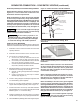
SEPARATED COMBUSTION – TWO PIPE VENTING
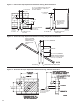
AIR INLET COLLAR
When unit is to be used in a separated vent system, the
inlet collar will be connected to the combustion air intake
pipe. The inlet collar is located on the bottom panel of size
50 units, and on the top panel of size 100-400 units. This
connection is made by using the appropriate size rubber
coupling (eld provided) for each size unit. The coupling
is installed so that air inlet pipe can be detached from the
unit for serviceability purposes.
COMBUSTION AIR VENTING AND PIPING
CARBON MONOXIDE!
Your venting system must not be blocked by
any snow, snow drifts, or any foreign matter.
Inspect your venting system to ensure adequate
ventilation exists at all times! Failure to heed
these warnings could result in Carbon Monoxide
Poisoning (symptoms include grogginess,
lethargy, inappropriate tiredness, or flu-like
symptoms).
1. The combustion air system installation must be in
accordance with the current edition of the National
Fuel Gas Code-NFPA 54 or ANSI Z223.1 National
Fuel Gas Code. In Canada, installation must be in
accordance with CSA-B149.1 “Installation Code for
Natural Gas Burning Appliances and Equipment” and
CSA-B149.2 “Installation Code for Propane Burning
Appliances and Equipment.”
2. Each unit heater MUST have its own combustion
air system. It MUST NOT be connected to other air
intake systems.
3. Use UL 1738 listed schedule 40 vent pipe for the
vent system. For installations in Canada, use UL-
S636 listed vent pipe conforming with local building
codes, or in the absence of local building codes,
with current CSA-B149.1 “Installation Codes for
Natural Gas Burning Appliances and Equipment” or
CSA-B149.2, “Installation Codes for Propane Gas
Burning Appliances and Equipment.”
Do not use Type B (double
wall) vent internally within the building on high
efciency unit heaters! This can result in death,
serious injury or substantial property damage.
Use of cellular core pipe for any
exhaust vent component is prohibited. Use of
cellular core pipe may result in severe personal
injury, death, or major property damage.
NOTICE: Installations in Canada require compliance
with ULC-S636 Standard for Type BH Gas Venting
Systems.
4. Long runs of single wall combustion air piping
passing through an unheated space may require
insulating if condensation becomes noticeable.
5. The combustion air inlet system must be installed
to prevent collection of condensate. Pitch horizontal
pipes downward 1/4 inch per foot (21 mm/m) toward
the inlet cap to facilitate drainage.
6. The equivalent length of the combustion air system
must not be less than 5 feet (1.5 m) and must not
exceed 50 feet (15.2 m). Equivalent length equals
the total length of straight pipe plus 5 feet (1.5 m) for
each 90 degree elbow and 2.5 feet (0.76 m) for each
45 degree elbow.
NOTICE: For optimum performance keep the
combustion air system as straight as possible.
7. A minimum vertical run of 12 inches (305 mm) is
required between the unit's ue vent connection and
rst elbow used.
8. Seal all vent pipe joints and seams to prevent
leakage. All joints must be cleaned prior to assembly.
Joints should then be primed in accordance with
ASTM F 656. After priming, joints should be
cemented per ASTM D 2564.
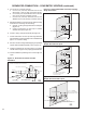
9. For horizontal combustion air systems longer than
5 feet (1.5 m), the system must be supported
from overhead building structures at 4 foot (1.2 m)
intervals in the U.S. and at 3 foot (0.91 m) intervals
in Canada.
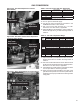
A eld provided stainless steel screen may be placed
on the inlet of the combustion air inlet pipe to prevent
animals from entering the venting system.
EXHAUST VENTING
For ue pipe installation, follow the steps in the STANDARD
COMBUSTION VENTING sections.
NOTE: For non-concentric venting (two wall or two roof penetrations, one for combustion air and a second for ue
pipe), follow the instructions below. For concentric venting (single wall or roof penetration), follow the concentric
venting instructions in SEPARATED COMBUSTION – CONCENTRIC VENTING Section.