
Nexus Manual
30
Note – In this mode all units will run at 100%
if the Master is given a W2 call.
Note – In this mode all units will run in fan
only mode it the master is given a G call.
f. Space Temperature Operation: The unit will
modulate from 100% re to the minimum input set by
the Run potentiometer (Run %) in order to maintain
the setpoint of the space temperature sensor.
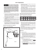
I. Space Temperature, Stand-alone: A W1
call will cause the unit to run at an input
determined by the Space Temperature
Setpoint potentiometer (Design T/Space SP),
and the current Space Temperature reading.
A 4 degree Fahrenheit deadband (+2/-2) and
run potentiometer (Run %) control are used to
determine when the unit res and the input at
which it runs.
• Both the OA DIP and IAR DIP Switch must
be ON to run in this mode.
• A space temperature sensor is required.
Note: If the unit was ordered with a modulating
gas control with room sensing (Direct Spark Gas
Control [GC] option 5), the space temperature
sensor is factory provided for eld installation.
• The minimum input is set with the RUN
potentiometer (Run %).
Note – A W1 Demand is required to enable
the unit in this mode.
Note – If a space temperature sensor is not
installed, or it is faulted, the unit will run at the
RUN potentiometer setting.
II. Space Temperature Networked, Global
enable: A W1 call will cause the Master to run at
an input determined by the Space Temperature
Setpoint potentiometer (Design T/Space SP),
and the current Space Temperature reading.
When the Master determines it should fire
based on the setpoint and space temperature,
it will broadcast the call and its calculated input
to all Members. All Member units will run at the
broadcast input level.
• The Master unit requires a space temperature
sensor. Note: If the unit was ordered with a
modulating gas control with room sensing
(Direct Spark Gas Control [GC] option 5), the
space temperature sensor is factory provided
for eld installation.
• The OA DIP and IAR DIP Switches as well
as the MASTER Switch must be ON for the
Master.
• The GLOBAL DIP Switch must be set to ON for
Members.
• Each Member uses its own RUN potentiometer
(Run %) for the lowest input level.
• All units must be connected using the Network
communication ports.
Note – When networking units together, the
Master and Member units need to be set to the
same Modbus address.
Note – If the broadcast input level is below
any Member’s RUN potentiometer setting, that
Member will run at its Run potentiometer setting.
Note – In this mode all units will run at 100% if
the Master is given a W2 call.
Note – In this mode all units will run in fan only
mode if the Master is given a G call.
g. 2-10 VDC/4-20 mA Input: The ring rate of the
unit can be controlled by a remote 4-20 mA or
2-10 VDC signal.
I. 2-10 VDC/4-20 mA Modulation Stand-alone:
An AUX call will cause the unit to run at an
input determined by the 2-10 VDC/4-20 mA
input. A value of 10 VDC/20 mA will cause the
unit to run at 100% and a value of 2 VDC/4 mA
will cause the unit to run at the minimum input.
• The VDC/mA Switch and jumper need to be
set for the correct signal type.
• The minimum input is set with the RUN
potentiometer (Run %).
II. 2-10 VDC/4-20 mA Modulation Networked:
An AUX call will cause the Master to run at an
input determined by the 2-10 VDC/4-20 mA
input. A value of 10 VDC/20 mA will cause the
unit to run at 100% and a value of 2 VDC/4
mA will cause the unit to run at the minimum
input. The Master will broadcast the call and
its calculated input to all Members. All Member
units will run at the broadcast input level.
• The MASTER Switch must be ON for the Master.
• The GLOBAL DIP Switch must be set to ON
for Members.
• Each Member uses its own RUN potentiometer
(Run %) for the lowest input level.
• All units must be connected using the
Network communication ports.
Note – When networking units together, the
Master and Member units need to be set to the
same Modbus address.
Note – If the broadcast input level is below
any Member’s RUN potentiometer setting, that
Member will run at its Run potentiometer setting.
Note – In this mode all units will run at 100% if
the Master is given a W2 call.
Note – In this mode all units will run in fan only
mode if the Master is given a G call.
h. Modbus Control: The operation of the unit can
be controlled by remote Modbus commands
over RS485. See the Modbus Register list
(Appendix A) for more information.
OPERATION – HIGH EFFICIENCY PROPELLER UNITS DIRECT SPARK IGNITION
(continued)